


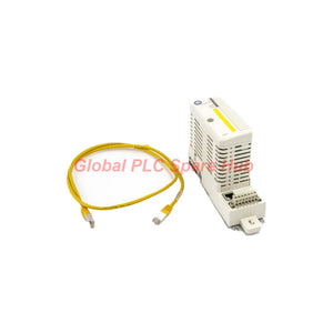
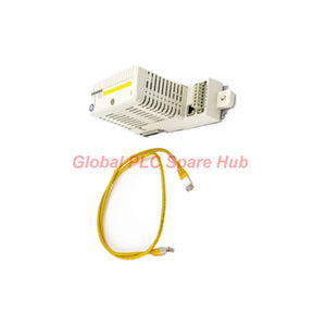

SM811K01 3BSE018173R1 ABB Safety CPU Module – SIL Safety Control
Manufacturer: ABB
Product No.: SM811K01
Condition: In stock
Product Type: CPU Module
Product Origin: SE
Payment: T/T, Western Union
Weight: 600g
Shipping port: Xiamen
Warranty: 12 months
Estimate delivery times: 12-26 days (International), 3-6 days (United States).
Return within 30 days of purchase. Duties & taxes are non-refundable.
Guaranteed Safe Checkout
ABB 3BSE018173R1 – SM811K01 Safety CPU Module
The ABB 3BSE018173R1 is an SM811K01 Safety CPU Module designed to collaborate with the PM865 controller in ABB safety systems. It supervises PM865 operation during SIL 1 and SIL 2 applications. Together, the SM811 and PM865 form a 1oo2 diverse architecture for SIL 3 applications.
The module connects to the CEX bus through a BC810 CEX bus interconnection box. Its MPC862P processor operates at 96 MHz and uses 32 MB of SDRAM. The hardware also supports redundant configurations, hot swapping, internal voltage monitoring, and overvoltage protection.
For redundant operation, the SM811 uses an SM Link synchronization connection. The supplied TK852V10 synchronization cable connects the corresponding SM Link interfaces. Status indicators help engineers verify module operation, fault conditions, primary assignment, and synchronization progress.
01 | System Architecture & Processing
- Manufacturer: ABB
- Model: 3BSE018173R1
- Module designation: SM811K01 Safety CPU Module
- Product function: Collaborating safety CPU
- Controller collaboration: PM865
- Processor: MPC862P, 96 MHz
- SDRAM: 32 MB
- Flash PROM: 4 MB for firmware storage
- Safety architecture: Supports PM865 supervision for SIL 1–2 and a 1oo2 diverse architecture for SIL 3
- Bus connection: CEX bus through BC810
- Redundancy interface: SM Link
- Hardware functions: Hot swap, redundancy support, internal voltage monitoring, and overvoltage protection
02 | Electrical & Interface Characteristics
CEX-Bus Power Consumption
- Nominal voltage: 24 V DC
- Typical current consumption: 160 mA
- Maximum current consumption: 250 mA
- Typical power dissipation: 3.8 W
Connector Configuration
- One 7-pin screw connector
- One RJ45 connector for SM Link
Electrical Input Characteristics
- Nominal voltage: 24 V
- Logic 0 voltage: -30 V < UL < 5 V
- Logic 1 voltage: 15 V < UH < 30 V
- Nominal current: 12 mA
- Input impedance: 1.8 kΩ
- Galvanic isolation: Yes
Electrical Output Characteristics
- Nominal voltage: 24 V
- Process voltage range: 12–32 V
- On-state output voltage: UP - 0.5 V < UA < UP
- Maximum continuous load current: 0.5 A
- Off-state output leakage current: < 10 mA
- Maximum short-circuit current: < 2.4 mA
- Output impedance: < 0.4 Ω
- Galvanic isolation: Yes
Insulation & Electrical Ratings
- Overvoltage category: II
- Rated insulation voltage: 50 V
- Insulation test voltage: 500 V AC for 1 minute
03 | Status Indicators & Diagnostic Interpretation
The front-panel LEDs provide operating information during commissioning and maintenance. Engineers can use these indications to distinguish controller operation, hardware faults, and synchronization states.
- F (Fault) / Red: Indicates a detected unit error. Control software manages the indication, while hardware sets and clears the state during controller reset.
- R (Run) / Green: Indicates operational status. Control software controls the indication, and hardware clears it during controller reset.
- Access EN (Enabled) / Yellow: Indicates that the Access Enable switch is active.
- DEGR (Degraded Mode) / Yellow: Reserved for future use.
- PRIM / Yellow: Identifies the SM811 assigned as the primary unit.
- SYNC (Synchronized) / Yellow: Indicates synchronization status. The LED flashes during the synchronization process and remains yellow when synchronization completes.
04 | Redundant Pair Synchronization
SM811 synchronization requires the correct SM Link connection and a defined activation sequence. Follow the equipment-specific engineering procedure and verify the controller state before starting.
- Check the synchronization cable: Confirm that the TK852V10 cable connects the SM Link ports of both SM811 modules.
- Insert the module: Install the SM811 in its designated position in accordance with the system procedure.
- Observe the SYNC LED: The LED flashes during startup and then follows a repeating three-flash-and-pause pattern.
- Trigger synchronization: Press the designated button to create an edge on digital input 3 of the running Safety Module.
- Monitor synchronization: The SYNC LED flashes faster while the synchronization process proceeds.
- Verify completion: The SYNC LED turns steady yellow when synchronization is complete.
Engineering note: Do not treat the initial flashing sequence as proof of completed synchronization. Confirm the final LED state and verify the redundant pair through the applicable system diagnostics before returning the system to service.
05 | Installation & Maintenance Considerations
- CEX bus topology: Check the BC810 interconnection arrangement and confirm that the module occupies the intended bus position.
- Power verification: Measure the 24 V DC supply and check that the CEX-Bus current capacity supports the installed configuration.
- Redundancy checks: Inspect the SM Link cable and connector seating before initiating synchronization.
- Module replacement: Although the hardware supports hot swap, follow the approved system procedure and application-specific safety requirements before removing or inserting a module.
- LED diagnostics: Record Fault, Run, Primary, and Sync indications when investigating controller or redundancy issues.
- Post-maintenance validation: Confirm controller supervision, redundant-pair status, and the expected safety-system operating state before handover.
06 | Mechanical Data
- Product net depth: 127.5 mm
- Product net height: 185 mm
- Product net width: 59 mm
- Product net weight: 0.6 kg

Tags
Q: Are these parts 100% original and new?
A: Yes. Every component is guaranteed to be 100% original, brand-new, and factory-sealed. We also provide a 12-month comprehensive warranty for your peace of mind.
Q: How fast is the shipping to my country?
A: For in-stock items, we offer same-day dispatch. International express shipping (DHL/FedEx/UPS) typically delivers within 3–5 business days worldwide.
Q: Can I get a formal quotation with shipping costs?
A: Absolutely. Our sales team is ready to provide a detailed Proforma Invoice (PI) including the most competitive shipping rates for your location.
Q: Do you offer discounts for bulk orders?
A: We provide volume-based pricing for large projects or multiple-item orders. Please contact us to get our Best Price Guarantee.
12-Month Comprehensive Warranty
Every part supplied by Global PLC Spare Hub is covered by a 12-month warranty from the date of invoice.
- Coverage: Functional defects and hardware failures under normal operating conditions.
- Commitment: We provide immediate repair, replacement, or a full refund for any verified defective components to minimize your operational downtime.
Returns & Exchange Policy
We offer a 30-day return policy to ensure you receive the exact part your system requires.
- Eligibility: Returns are accepted for uninstalled items in their original, factory-sealed packaging.
- RMA Process: Please contact our support team to obtain a Return Merchandise Authorization (RMA) number before shipping.
- Fast Processing: Refunds or exchanges are processed within 3–5 business days after the returned item passes our technical inspection.
Need Technical Assistance?Not sure if this part is compatible with your system? [Consult our Engineers] before purchasing to ensure 100% compatibility.
People Also Bought


