


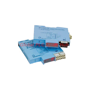
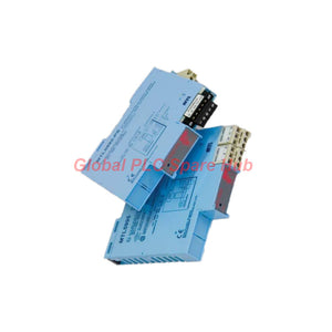
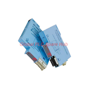
MTL5995 Fieldbus Power Supply | MTL H1 Series Reliable 19V Output
Manufacturer: MTL
Product No.: MTL5995
Condition: In stock
Product Type: Power Supply Module
Product Origin: EN
Payment: T/T, Western Union
Weight: 300g
Shipping port: Xiamen
Warranty: 12 months
Estimate delivery times: 12-26 days (International), 3-6 days (United States).
Return within 30 days of purchase. Duties & taxes are non-refundable.
Guaranteed Safe Checkout
MTL5995 Fieldbus Power Supply — Stable H1 Segment Power for Industrial Networks
The MTL5995 is a general-purpose power supply for 31.25 kbit/s H1 fieldbus systems. It provides a regulated 19 V DC output for compatible fieldbus segments. Its low output impedance supports stable power delivery to connected devices.
The unit follows Fieldbus Foundation power supply Type 131 requirements. This non-intrinsically safe supply is intended to feed an intrinsically safe barrier. Engineers must verify the complete segment design before connecting hazardous-area instruments.
The MTL5995 provides a design current of up to 350 mA. Its current limit exceeds 370 mA, providing additional inrush margin. This design helps prevent other devices from resetting when an instrument disconnects or reconnects on a fully loaded segment.
The product family includes two connector configurations: MTL5995 and MTL5995-PS. The PS version provides a single secured plug-in fieldbus connector and a power plug. The manufacturer recommends this configuration for new installations.
01 | Product Identity and Variant Selection
| Item | Details |
|---|---|
| Manufacturer Brand | MTL |
| Product Family | MTL5995 H1 Fieldbus Power Supply |
| Model A | MTL5995 |
| Model B | MTL5995-PS |
| Product Type | Fieldbus segment power supply |
| Network Standard | 31.25 kbit/s H1 fieldbus |
| Power Supply Classification | Fieldbus Foundation Type 131, non-IS supply intended to feed an IS barrier |
| Installation Location | Safe area or suitably approved Zone 2 / Class I Division 2 location |
| Recommended New Installation Variant | MTL5995-PS |
Variant difference: The MTL5995 uses a pair of plug-in fieldbus connectors. The MTL5995-PS uses one secured plug-in fieldbus connector and a separate power plug. Check the installed wiring arrangement before ordering a replacement.
02 | Electrical Performance at a Glance
| Electrical Parameter | Specified Value |
|---|---|
| DC Input Voltage | 20–30 V DC |
| Regulated Output Voltage | 19 V ±2% |
| DC Output Impedance | Less than 2 Ω |
| Design Output Current | 0–350 mA |
| Current Limit | Greater than 370 mA |
| Output Ripple | Complies with Fieldbus requirements under clause 22.6.2 for output currents above 10 mA |
| Isolation | 250 V RMS between fieldbus and power supply terminals |
| Power Indication | One green LED |
| Internal Bus Termination | Selectable using the switch at the base of the unit |
Engineering note: The 350 mA design current and greater-than-370 mA current limit serve different purposes. The design current defines the specified operating range. The current limit provides additional margin for device inrush.
03 | Input Loading and Heat Dissipation
Supply sizing must account for input current and thermal losses. The following figures apply at a 350 mA output load.
| Input Voltage | Typical Input Current | Power Dissipation |
|---|---|---|
| 20 V DC | 520 mA | Not specified in the supplied data |
| 24 V DC | 420 mA | 3.4 W typical |
| 30 V DC | 370 mA | 4.5 W maximum |
- Maintain an input supply within the specified 20–30 V DC range.
- Allow sufficient power capacity for the fieldbus load and the supply's input requirements.
- Install the module with 10 mm clearance from adjacent units.
- Use MTL MS010 spacers when the installation requires the specified 10 mm separation.
- Check cabinet ventilation and surrounding temperatures during system design.
04 | Fieldbus Wiring and Terminal Reference
| Terminal | Function | Model Applicability |
|---|---|---|
| 7 | Internally linked to terminal 10; assists with cable-screen termination | MTL5995 |
| 8 and 11 | Fieldbus device connections, negative | Both variants |
| 9 and 12 | Fieldbus device connections, positive | Both variants |
| 10 | Internally linked to terminal 7 on MTL5995; cable-screen interconnection terminal on MTL5995-PS | Variant-dependent |
| 13 | DC supply negative | Both variants |
| 14 | DC supply positive | Both variants |
Terminal functions differ in their cable-screen arrangements. Follow the correct wiring diagram for the exact model. Do not assume that terminals 7 and 10 provide identical arrangements on both versions.
05 | Mechanical and Environmental Limits
- Mounting: 35 mm DIN rail, top-hat type.
- Rail standards: EN 50022-35 × 7.5, BS 5584, and 35 × 27 × 7.3 DIN 46277.
- Operating temperature: −20°C to +60°C.
- Storage temperature: −40°C to +80°C.
- Relative humidity: 5–95%.
- Approximate weight: 110 g.
- Fieldbus-to-supply isolation: 250 V RMS.
- Installation clearance: 10 mm from adjacent units.
The terminal conductor range depends on the model. The MTL5995 accepts 0.14–2.5 mm² conductors. The MTL5995-PS accepts 0.14–1.5 mm² conductors. Both support stranded or single-core conductors.
06 | Bus Termination and Network Integration
Correct termination is essential for reliable H1 fieldbus communication. Each bus segment requires termination at both ends.
- Use the internal termination switch when the supply occupies one end of the trunk.
- Use a compatible external terminator when the supply does not occupy a segment endpoint.
- Suitable listed options include the MTL FBT1-IS, F100, and FCS-MBT terminators.
- Confirm the terminator type against the segment design and hazardous-area requirements.
- Check polarity, trunk topology, cable screening, and total segment loading before commissioning.
The internal termination switch does not replace the requirement for two correctly positioned bus terminators. An incorrect termination arrangement can cause communication errors even when the supply voltage remains stable.
07 | Supported Systems and Typical Applications
The MTL5995 supports compatible 31.25 kbit/s H1 fieldbus installations. Its suitability depends on the network architecture, connected device load, and hazardous-area design.
- Process instrumentation: Powering compatible H1 fieldbus segments with multiple field instruments.
- Oil and gas facilities: Supporting fieldbus infrastructure in appropriately designed process areas.
- Chemical plants: Supplying compatible fieldbus networks serving process measurement devices.
- Water and wastewater: Supporting distributed instrumentation on H1 fieldbus segments.
- Process control systems: Providing segment power for compatible fieldbus instruments and approved barrier arrangements.
- Control cabinet upgrades: Replacing a supply after checking its connector version, current capacity, termination arrangement, and approvals.
The module is a segment power supply, not a fieldbus host, controller, or protocol gateway. It does not independently perform instrument configuration or network communication diagnostics.
08 | Diagnostics and Field Troubleshooting
The MTL5995 has one green power LED. This indicator confirms a power-related status but does not provide detailed device-level diagnostics.
- Green LED off: Check the incoming DC supply, polarity, terminal tightness, and upstream protection.
- Field instruments lose communication: Measure the supply voltage and inspect the segment load, wiring, and termination.
- Devices reset during reconnection: Review the total segment current and the inrush characteristics of connected instruments.
- Intermittent communication faults: Inspect cable screening, connectors, trunk topology, and both end terminators.
- Unexpected voltage drop: Check conductor resistance, terminal condition, cable length, and total connected load.
Practical example: Several H1 instruments may become unstable after a replacement device connects to a heavily loaded segment. Check the total current against the 350 mA design limit first. Then verify the incoming supply and segment termination. This sequence helps distinguish power-loading problems from communication-layer faults.
Important limitation: The green LED cannot identify a faulty field instrument or confirm communication quality. Use a suitable fieldbus diagnostic tool or host-system diagnostics for device-level investigation.
09 | Global PLC Spare HUB's Insight
For fieldbus supply selection, engineers should evaluate three separate factors: electrical capacity, network termination, and hazardous-area compliance. Matching the output voltage alone does not guarantee a suitable replacement.
Field experience: reconnecting a device on a loaded segment
When a field instrument reconnects, its input circuitry may draw additional current during startup. The MTL5995 provides a current limit above 370 mA to create inrush margin beyond its 350 mA design current. This feature helps reduce the risk of disturbing other devices during reconnection.
However, the margin does not authorise continuous operation above the specified design current. Calculate the steady-state load for all connected devices and check their startup requirements. Investigate repeated resets if the segment approaches its current limit.
Field experience: stable voltage but unreliable communication
A fieldbus segment can show a reasonable DC voltage while communication remains unstable. Incorrect termination, poor screen connections, and unsuitable trunk wiring can produce similar symptoms. Check both segment endpoints before replacing the power supply.
Selection recommendation: Choose MTL5995 when its paired plug-in connector arrangement matches the installed design. Consider MTL5995-PS for new installations requiring its secured fieldbus connector and separate power plug. Verify terminal wiring and certification before ordering either version.
10 | Hazardous-Area Approvals and Standards
The supplied specification lists the following approvals and installation classifications. Approval details differ between the two variants.
| Approval or Requirement | Specified Information |
|---|---|
| Module Location | Safe area, Zone 2 IIC T4, or Class I Division 2 Groups A–D T4 location, subject to applicable approval |
| Field Wiring Location | Safe area, Zone 2 IIC T4, or Class I Division 2 Groups A–D T4 location, subject to applicable approval |
| Field Wiring Protection | Normally non-arcing / Ex nA |
| ATEX — MTL5995 | EN 50021, II 3 G Ex nA IIC T4 |
| ATEX — MTL5995-PS | IEC 60079-15, II 3 G Ex nA IIC T4 |
| FM — United States | Class No. 3611, Class I Division 2 Groups A–D |
| CSA — Canada | C22.2 No. 213, Class I Division 2 Groups A–D; Ex nA IIC T4 |
| Applicable Fieldbus References | FF-816, IEC 61158-2:1993, and ISA-S50.02-1992 |
These details reflect the supplied product documentation. Confirm the current certificate, exact model suffix, installation conditions, and local regulatory requirements before use in a hazardous area.
11 | Purchasing, Packaging, and Warranty
- Product identification: MTL5995 or MTL5995-PS, according to the order.
- Quantity: One unit unless the quotation specifies otherwise.
- Accessories: Terminators, spacers, and additional wiring accessories are not included unless explicitly listed.
- Documentation: Available product documentation depends on the supplied package and order terms.
- Warranty: 12 months under the agreed sales terms.
- Dispatch: Typically 24–48 hours after order confirmation, subject to stock availability and payment clearance.
- Courier options: FedEx, UPS, and DHL, subject to destination and service availability.
Contact Global PLC Spare HUB to confirm the exact variant, stock status, quotation, and delivery arrangements. Provide your destination country and required quantity for an accurate shipping estimate.
12 | Frequently Asked Questions
Q1: How should engineers calculate the maximum number of fieldbus instruments for this supply?
Calculate the combined steady-state current of all connected devices and keep the total within the 350 mA design current. Also consider startup current, cable voltage drop, barrier losses, and the network design requirements. The number of instruments depends on their individual current consumption.
Q2: Can the internal terminator remain enabled when an external terminator is installed nearby?
Only if the network design places the supply at a segment endpoint and the termination arrangement remains correct. Each bus requires termination at both ends. Avoid adding extra terminators without reviewing the complete trunk topology.
Q3: What should be checked before using the MTL5995 with an intrinsically safe barrier?
Confirm that the supply and barrier arrangement matches the manufacturer's approved system design. Review the barrier's input requirements, output characteristics, segment current, entity parameters, and hazardous-area documentation. The MTL5995 is a non-IS supply intended to feed an IS barrier; it does not replace the barrier.
Q4: How can engineers distinguish a supply problem from a fieldbus wiring problem?
Measure the DC input and segment output under normal operating load. Compare these readings with the specified voltage and load limits. If supply conditions remain acceptable, inspect termination, cable screening, polarity, connectors, and host-system diagnostics. Use a fieldbus analyser when the fault remains unclear.
Q5: Which model should buyers select for a new cabinet or an existing replacement?
For a new installation, consider the MTL5995-PS because its connector arrangement is recommended for new installations. For a replacement, match the installed model, terminal wiring, cable-screen arrangement, mounting requirements, and certification. Confirm the exact part number before placing the order.
Request a Quote for MTL5995 / MTL5995-PS
Looking for an MTL5995 or MTL5995-PS fieldbus power supply? Contact Global PLC Spare HUB for current pricing, availability, model verification, and shipping options.
Send us your part number, quantity, destination, and application requirements. Our team can help verify the connector configuration and key electrical specifications before you order.

Tags
Q: Are these parts 100% original and new?
A: Yes. Every component is guaranteed to be 100% original, brand-new, and factory-sealed. We also provide a 12-month comprehensive warranty for your peace of mind.
Q: How fast is the shipping to my country?
A: For in-stock items, we offer same-day dispatch. International express shipping (DHL/FedEx/UPS) typically delivers within 3–5 business days worldwide.
Q: Can I get a formal quotation with shipping costs?
A: Absolutely. Our sales team is ready to provide a detailed Proforma Invoice (PI) including the most competitive shipping rates for your location.
Q: Do you offer discounts for bulk orders?
A: We provide volume-based pricing for large projects or multiple-item orders. Please contact us to get our Best Price Guarantee.
12-Month Comprehensive Warranty
Every part supplied by Global PLC Spare Hub is covered by a 12-month warranty from the date of invoice.
- Coverage: Functional defects and hardware failures under normal operating conditions.
- Commitment: We provide immediate repair, replacement, or a full refund for any verified defective components to minimize your operational downtime.
Returns & Exchange Policy
We offer a 30-day return policy to ensure you receive the exact part your system requires.
- Eligibility: Returns are accepted for uninstalled items in their original, factory-sealed packaging.
- RMA Process: Please contact our support team to obtain a Return Merchandise Authorization (RMA) number before shipping.
- Fast Processing: Refunds or exchanges are processed within 3–5 business days after the returned item passes our technical inspection.
Need Technical Assistance?Not sure if this part is compatible with your system? [Consult our Engineers] before purchasing to ensure 100% compatibility.
People Also Bought


