


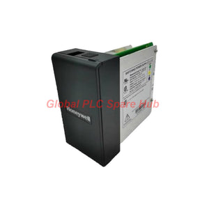
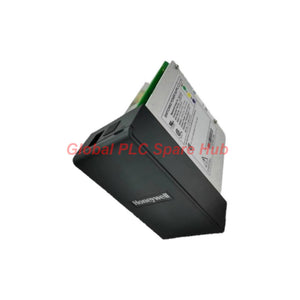
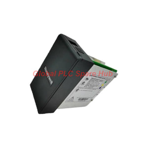
900P24-0501 Honeywell Power Supply Module 24VDC
Manufacturer: Honeywell
Product No.: 900P24-0501
Condition: In stock
Product Type: Power Supply Module
Product Origin: USA
Payment: T/T, Western Union
Weight: 500g
Shipping port: Xiamen
Warranty: 12 months
Estimate delivery times: 12-26 days (International), 3-6 days (United States).
Return within 30 days of purchase. Duties & taxes are non-refundable.
Guaranteed Safe Checkout
900P24-0501 Honeywell 24VDC Power Supply
The Honeywell 900P24-0501 is a 24 VDC power supply designed for industrial control power applications. It accepts an operating voltage range of 21–29 VDC and provides up to 5 A of continuous current, subject to the specified operating conditions.
For maintenance and system replacement projects, engineers should evaluate the supply's output capacity, input power requirement, inrush behavior, hold-up time, terminal wiring, and ambient temperature limits. These parameters help determine whether the unit suits the target control cabinet and connected load.
01 | Electrical Performance Profile
| Parameter | Specification | Engineering Relevance |
|---|---|---|
| Manufacturer | Honeywell | Confirm the catalog number against the installed control system documentation. |
| Model | 900P24-0501 | Use the complete model number for procurement and replacement checks. |
| Product Type | 24 VDC power supply | Provides DC power for compatible industrial control equipment. |
| Operating Voltage | 21–29 VDC | Check voltage at the supply terminals under actual load. |
| Maximum Continuous Current | 5 A | Size the supply against the combined steady-state load and applicable derating. |
| Input Rating | 72.5 W | Consider input power requirements when assessing cabinet power capacity. |
| Output Rating | 51 W | Check the stated power rating alongside voltage and current limits. |
| Inrush Current | 30 A for 3 ms at 29 VDC | Consider transient current when evaluating upstream protection and power distribution. |
| Hold-Up Time | 20 ms at 24 VDC, maximum load | Provides a short ride-through interval during a brief interruption, under the stated test condition. |
| Fuse | Internal, non-replaceable | Internal fuse failure may require unit replacement or manufacturer-authorized service. |
| Wiring Terminals | Screw-type terminals | Use compatible conductors and follow the applicable terminal torque specification. |
| Conductor Size | 0.3–3.3 mm², #22–12 AWG | Select wiring appropriate for current, installation method, and local electrical requirements. |
| Ambient Temperature | 0°C to 51°C, T4 as supplied | Maintain the specified ambient range and verify the meaning of the T4 designation for the installation. |
02 | Power Budget: What Engineers Should Verify
The stated maximum continuous current is 5 A, while the listed output rating is 51 W. At a nominal 24 VDC, 51 W corresponds to approximately 2.13 A. These figures should not be treated as interchangeable limits without checking the manufacturer's full specification.
- Confirm the rated output: Verify whether 51 W applies to a specific operating condition or represents the applicable maximum output power.
- Calculate the actual load: Add the steady-state current requirements of all connected devices, including controllers, communication interfaces, relays, and field instruments.
- Allow for transient loads: Account for startup demand from connected equipment and ensure the supply can support the expected load profile.
- Check voltage drop: Measure voltage at the receiving device, not only at the power supply, particularly when wiring runs are long.
- Review protection: Confirm that upstream protective devices can accommodate the specified inrush current while providing appropriate fault protection.
Important: Do not assume that the 5 A continuous-current figure permits a 120 W output at 24 VDC. The listed 51 W output rating requires confirmation against the applicable Honeywell documentation before final load sizing.
03 | Where This Power Supply May Be Used
| Equipment or System | Potential Application | Pre-Installation Check |
|---|---|---|
| Industrial control cabinets | DC power distribution for compatible control components | Verify mounting, wiring, ventilation, and available cabinet space. |
| PLC and process-control panels | Powering supported control-system components where the electrical interface is approved | Confirm the specific controller or system hardware requires this supply model. |
| Distributed control system installations | Replacement or maintenance of an appropriately specified 24 VDC supply | Check the rack or system power architecture and the approved replacement list. |
| Industrial communication equipment | DC power for compatible communication interfaces or auxiliary devices | Confirm voltage tolerance, peak current, grounding, and load requirements. |
| Process instrumentation panels | Power distribution for supported low-voltage control and instrumentation devices | Verify total load, signal isolation needs, and required supply stability. |
| Plant maintenance and spares inventory | Replacement planning for equipment using the same catalog number | Match the full part number and applicable hardware revision. |
These are potential application categories, not confirmation that every listed device is compatible. Verify the target equipment's approved power-supply requirements before connecting the unit.
04 | Installation Notes for Control Technicians
- Inspect before installation: Check the label, terminal condition, enclosure, and model number against the maintenance work order.
- Isolate power: Follow site lockout procedures and verify that the circuit is de-energized before wiring or removing the supply.
- Size the conductors: Use the stated 0.3–3.3 mm² (#22–12 AWG) range, then confirm conductor suitability and terminal torque in the product documentation.
- Check polarity: Confirm DC positive and negative terminal assignments from the unit markings. Do not rely on wire color alone.
- Measure under load: After commissioning, verify the DC voltage at both the supply output and the connected load.
- Check cabinet temperature: Keep the ambient temperature within the specified 0°C to 51°C range and assess heat from adjacent equipment.
- Review startup behavior: Observe whether upstream protection trips when the supply energizes. Consider the specified 30 A, 3 ms inrush condition during protection coordination.
05 | Troubleshooting and Diagnostic Guide
| Symptom | Possible Cause | Diagnostic Approach |
|---|---|---|
| No DC output | Missing input power, wiring fault, internal fuse failure, or a failed supply | Verify the source voltage and wiring first. If input conditions are correct, follow the manufacturer's test procedure. Do not attempt to replace the internal non-replaceable fuse. |
| Output voltage drops under load | Excessive load, loose terminals, conductor voltage drop, or supply malfunction | Measure voltage at the supply and load terminals under operating conditions. Check the load budget and terminal connections. |
| Upstream protection trips during startup | Inrush current, unsuitable protective-device characteristics, or a wiring fault | Compare the protection device's response with the stated inrush profile. Inspect for wiring faults before changing protection settings. |
| Connected devices reset intermittently | Brief supply interruption, transient loading, loose wiring, or voltage sag | Trend the DC voltage during startup and switching events. Check load changes and terminal integrity. The 20 ms hold-up figure applies at 24 VDC under maximum load. |
| Power supply runs in a hot cabinet | High ambient temperature, restricted airflow, or excessive loading | Measure cabinet ambient temperature, review the connected load, and improve ventilation where the cabinet design permits. |
| Repeated supply failures | Overload, repeated transients, poor connections, or unsuitable operating conditions | Record failure timing, load current, input conditions, and temperature. Investigate the root cause before installing a replacement. |
Diagnostic limitation: The supplied specifications do not establish built-in diagnostic indicators, communication-based monitoring, or remote alarm capabilities. Use external voltage and current measurements and the applicable system diagnostics rather than assuming the supply reports its own fault status.
06 | Global PLC Spare HUB's Insight
For control-system maintenance, the key selection issue is not voltage alone. The 900P24-0501 lists a 21–29 VDC operating range, a maximum continuous current of 5 A, and a 51 W output rating. The current and power figures should be checked together against the manufacturer's rated operating conditions.
- When replacing an installed unit: Match the full model number and confirm that the replacement meets the target system's mechanical and electrical requirements.
- When investigating unexplained resets: Measure voltage at the load during switching and startup. A normal unloaded reading does not rule out voltage sag under operating conditions.
- When reviewing protection: Account for the stated 30 A inrush current lasting 3 ms at 29 VDC. Check the upstream protective device and wiring arrangement before attributing startup trips to a defective supply.
- When building spare stock: Keep the full catalog number in the inventory record and document verified compatibility with the installed hardware.
The most useful pre-purchase step is to confirm the official output-power limits and system compatibility. This prevents a replacement decision based on nominal voltage or maximum current alone.
07 | Global PLC Spare HUB Review
The Honeywell 900P24-0501 is a candidate for maintenance and replacement projects that specifically call for this 24 VDC power-supply model. Its stated operating range, continuous-current limit, short hold-up time, and screw-terminal wiring details provide a practical starting point for electrical review.
Before ordering, confirm the 51 W output rating, the actual connected load, upstream inrush tolerance, and the target system's approved hardware requirements. Since the internal fuse is non-replaceable, a suspected internal failure should be handled through the manufacturer's recommended service or replacement procedure.
08 | Warranty and Shipping
- Warranty: 12-month warranty, subject to the applicable seller warranty terms.
- Shipping options: FedEx, UPS, and DHL, subject to destination and service availability.
- Order verification: Please provide the complete model number and target equipment details to support compatibility review.
- Quotation support: Contact Global PLC Spare HUB for current pricing, availability, and order information.
09 | Frequently Asked Questions
Q1: Can I size this unit using the 5 A rating alone?
A: No. The supplied information also lists a 51 W output rating. At 24 VDC, 51 W is approximately 2.13 A, so confirm the manufacturer's rated output conditions before calculating the permissible load. Use the verified power and current limits, not whichever figure appears larger.
Q2: What is the best way to distinguish a faulty supply from a downstream wiring problem?
A: Measure the output at the supply terminals and at the receiving device while the system is operating. If the supply output remains stable but the load voltage drops, inspect conductor sizing, terminal connections, and circuit loading. If the supply output itself falls, check the load demand and input conditions before concluding that the unit has failed.
Q3: Will the 20 ms hold-up time prevent every controller reset during a power interruption?
A: No. The stated hold-up time applies at 24 VDC under maximum load. Actual ride-through depends on interruption duration, load profile, wiring, and the connected controller's minimum operating voltage. Test the complete power path under the expected interruption conditions.
Q4: What should I check if an upstream breaker trips only when the supply starts?
A: Review the supply's specified 30 A inrush current for 3 ms at 29 VDC, then compare it with the protective device's characteristics and the rest of the circuit. Inspect wiring and downstream faults first. Do not increase the breaker rating without confirming conductor protection and applicable electrical requirements.
Q5: What details help confirm that this is the correct replacement part?
A: Provide the full 900P24-0501 catalog number, the equipment or panel where it is installed, the existing supply label, and the measured load requirements. If the original unit failed, include the symptoms and operating conditions. These details support a more reliable compatibility review than matching a generic 24 VDC rating alone.
Request a Quote
Looking for the Honeywell 900P24-0501 24VDC Power Supply? Contact Global PLC Spare HUB with your required quantity and equipment details to request pricing, availability, and compatibility support.
Tags
Q: Are these parts 100% original and new?
A: Yes. Every component is guaranteed to be 100% original, brand-new, and factory-sealed. We also provide a 12-month comprehensive warranty for your peace of mind.
Q: How fast is the shipping to my country?
A: For in-stock items, we offer same-day dispatch. International express shipping (DHL/FedEx/UPS) typically delivers within 3–5 business days worldwide.
Q: Can I get a formal quotation with shipping costs?
A: Absolutely. Our sales team is ready to provide a detailed Proforma Invoice (PI) including the most competitive shipping rates for your location.
Q: Do you offer discounts for bulk orders?
A: We provide volume-based pricing for large projects or multiple-item orders. Please contact us to get our Best Price Guarantee.
12-Month Comprehensive Warranty
Every part supplied by Global PLC Spare Hub is covered by a 12-month warranty from the date of invoice.
- Coverage: Functional defects and hardware failures under normal operating conditions.
- Commitment: We provide immediate repair, replacement, or a full refund for any verified defective components to minimize your operational downtime.
Returns & Exchange Policy
We offer a 30-day return policy to ensure you receive the exact part your system requires.
- Eligibility: Returns are accepted for uninstalled items in their original, factory-sealed packaging.
- RMA Process: Please contact our support team to obtain a Return Merchandise Authorization (RMA) number before shipping.
- Fast Processing: Refunds or exchanges are processed within 3–5 business days after the returned item passes our technical inspection.
Need Technical Assistance?Not sure if this part is compatible with your system? [Consult our Engineers] before purchasing to ensure 100% compatibility.
People Also Bought


