


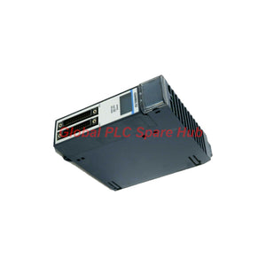
IC694MDL753 PACSystems RX3i Positive Logic Output Module | 12/24VDC
Manufacturer: GE Fanuc
Product No.: IC694MDL753
Condition: In stock
Product Type: Voltage Output Module
Product Origin: USA
Payment: T/T, Western Union
Weight: 500g
Shipping port: Xiamen
Warranty: 12 months
Estimate delivery times: 12-26 days (International), 3-6 days (United States).
Return within 30 days of purchase. Duties & taxes are non-refundable.
Guaranteed Safe Checkout
IC694MDL753 | GE Fanuc PACSystems RX3i High-Density Positive Logic Output Module
The GE Fanuc IC694MDL753 is a 32-point high-density discrete output module for the PACSystems RX3i platform. It provides 12/24 VDC positive logic outputs for industrial control applications.
The module organizes its 32 output channels into four independent groups. Each group contains eight output points, supporting distributed load connections within one I/O module.
Each channel supports up to 0.5 A output current. The module provides a maximum output response time of 0.5 ms for both ON and OFF transitions.
Originally developed under GE Intelligent Platforms, this product belongs to the GE Fanuc RX3i hardware family. Emerson Automation is the current platform brand.
01 | Hardware Identity and System Architecture
| Brand | GE Fanuc / Emerson |
| Manufacturer | GE Intelligent Platforms (historical); Emerson Automation (current) |
| Model | IC694MDL753 |
| Product Series | PACSystems RX3i |
| Product Type | High-Density Discrete Output Module |
| Output Configuration | Positive Logic / Sourcing |
| Number of Output Points | 32 |
| Number of Output Groups | 4 |
| Points per Group | 8 |
| Nominal Operating Voltage | 12/24 VDC |
| Installation Location | RX3i PACSystems I/O Slot |
| Module Occupancy | 1 I/O slot |
02 | Output Characteristics and Electrical Performance
The module uses positive logic switching to supply DC voltage to connected field loads. Its four-group architecture supports organized distribution of output circuits.
| Output Voltage Range | 10.2–28.8 VDC |
| Nominal Output Voltage | 12/24 VDC |
| Output Current per Point | 0.5 A maximum |
| Maximum Output Current per Group | 4 A |
| Group Common Pin Rating | 3 A maximum |
| Switching Current per Group | 3 A maximum |
| Inrush Current | 5.4 A for 10 ms |
| ON-State Voltage Drop | 0.3 VDC maximum |
| OFF-State Leakage Current | 0.1 mA maximum |
| Maximum ON Response Time | 0.5 ms |
| Maximum OFF Response Time | 0.5 ms |
| Backplane Current Consumption | 260 mA maximum at 5 VDC |
Load design consideration: The per-point, group, and common-pin current ratings impose separate limitations. Engineers must observe the applicable limits simultaneously when calculating the output load.
03 | Four-Group Output Distribution
The 32 output points follow a four-group arrangement. Each group contains eight independently controlled channels.
- Group 1: Eight positive logic output channels.
- Group 2: Eight positive logic output channels.
- Group 3: Eight positive logic output channels.
- Group 4: Eight positive logic output channels.
This arrangement supports separate load circuits within one module. Engineers can plan different DC load circuits across groups, subject to the specified voltage and current limitations.
For example, a control cabinet may allocate separate groups to valve solenoids, relay interfaces, indicator circuits, and auxiliary actuators. Each circuit requires an independent load calculation.
04 | Isolation and Electrical Protection
Electrical isolation helps separate the field wiring from the PLC backplane. Group isolation also supports the electrical separation requirements of the output architecture.
| Field-to-Backplane Isolation | 250 VAC continuous; 1500 VAC for 1 minute |
| Field-to-Frame Ground Isolation | Optical isolation; 250 VAC continuous, 1500 VAC for 1 minute |
| Group-to-Group Isolation | 50 VAC continuous; 500 VAC for 1 minute |
| Output Logic | Positive Logic |
| OFF-State Leakage | 0.1 mA maximum |
Observe the specified isolation limits when designing field wiring. Do not treat group isolation as permission to exceed the rated voltage between circuits.
05 | Backplane Consumption and Status Monitoring
The module draws its internal operating power from the RX3i backplane. Field-side power supplies provide the voltage required by the connected output loads.
- Backplane voltage: 5 VDC.
- Maximum backplane current: 260 mA.
- Group consumption at 24 VDC: 16.5 mA maximum per group with all eight outputs ON.
- Group consumption at 12 VDC: 9.6 mA maximum per group with all eight outputs ON.
- Channel indication: 32 individual LED indicators.
The 32 LEDs provide individual output status indication. Technicians can compare commanded output states with visible channel indications during commissioning and troubleshooting.
LED status alone does not confirm that a field load receives the correct voltage. Use electrical measurements when investigating output circuit problems.
06 | Wiring Interface and Cable Compatibility
The IC694MDL753 uses two 24-pin connector interfaces. These interfaces support compatible pre-wired cables or suitable user-built wiring assemblies.
| Connector Arrangement | Two male 24-pin connector interfaces |
| Connector Type | Fujitsu FCN-365P024-AU compatible |
| Compatible Cable 1 | IC694CBL327 |
| Compatible Cable 2 | IC694CBL328 |
| Wiring Configuration | Positive Logic |
Positive logic outputs source the positive DC supply to the connected load. The load return connects to the appropriate DC common.
Before wiring, verify connector pin assignments and group common connections. Follow the RX3i installation documentation for terminal mapping and field power distribution.
07 | Installation and Commissioning Procedure
The module occupies one RX3i I/O slot. It supports installation in compatible local or remote I/O racks.
- Check rack compatibility: Verify the chassis supports the selected RX3i I/O configuration.
- Inspect the module: Check the connector interfaces and module housing.
- Confirm slot assignment: Verify the intended I/O slot in the hardware configuration.
- Install the module: Follow the chassis installation procedure.
- Connect field wiring: Use the specified pre-wired cable or approved wiring assembly.
- Verify field power: Confirm the DC supply voltage and polarity.
- Check output allocation: Match PLC logic addresses with the physical output channels.
- Test individual points: Verify LED indication and field load response.
- Check group loading: Confirm current limits for every output group.
CPU STOP mode consideration: The supplied technical references contain conflicting descriptions of output behavior during CPU STOP transitions. Do not assume an automatic ON or OFF state. Verify the configured fault response and applicable hardware manual before commissioning safety-related or interlocked circuits.
08 | Field Diagnostics and Maintenance Recommendations
Output faults can originate from the module, field power supply, wiring, or connected load. A systematic diagnostic sequence helps isolate the actual cause.
| Observed Condition | Recommended Engineering Check |
| Output LED remains OFF | Check PLC logic, channel addressing, and module status. |
| LED is ON but load does not operate | Measure field voltage and inspect the load return path. |
| Unexpected output voltage drop | Check load current and the 0.3 V maximum ON-state drop. |
| Intermittent load operation | Inspect field wiring, connector seating, and supply stability. |
| Multiple channels fail together | Investigate group common connections and field supply distribution. |
| Excessive field circuit current | Check for short circuits and overloaded output groups. |
During preventive maintenance, inspect connector contacts and cable insulation. Compare measured output behavior with the PLC program and the expected load characteristics.
09 | System Compatibility and Selection Guidance
The IC694MDL753 belongs to the GE Fanuc PACSystems RX3i discrete output family. Correct selection requires both hardware and electrical compatibility checks.
- Platform: PACSystems RX3i.
- Rack position: Compatible local or remote I/O slot.
- Output type: 12/24 VDC positive logic sourcing output.
- Channel count: 32 discrete output points.
- Group arrangement: Four groups with eight points each.
- Wiring: IC694CBL327 or IC694CBL328 compatible cables.
- Power budget: Allow at least the specified maximum 260 mA backplane current.
Do not confuse this model with RX3i input modules or negative logic output modules. Their electrical interfaces and field wiring requirements differ.
10 | Five Professional Engineering FAQs
Q1: How should engineers allocate inductive loads across the four output groups?
Distribute loads according to their steady-state current and startup characteristics. Pay particular attention to solenoids, contactors, and other inductive devices. Check suppression requirements and verify that every group remains within its current limits.
Q2: Can a PLC output LED confirm that a connected solenoid has received sufficient operating current?
No. The LED indicates the channel's output status, not the actual current through the load. Measure the field voltage and current when diagnosing solenoid operation. Also inspect the return connection and the condition of the coil.
Q3: What is the practical impact of the 0.1 mA maximum OFF-state leakage current?
High-impedance electronic loads may respond to small leakage currents. This can produce unexpected voltage readings or faint indicator illumination. Evaluate the load input characteristics when investigating apparent OFF-state activation.
Q4: How should engineers handle loads with high startup current?
Compare the load's inrush profile with the specified 5.4 A rating for 10 ms. Also check the continuous channel and group current limits. Consider suitable interposing relays when the load exceeds the module's electrical ratings.
Q5: What should technicians investigate when all eight channels in one group stop operating?
Start with the group's common connection and external DC supply. Check the connector contacts and field wiring for loose connections. Then test individual loads and verify the PLC output commands. A shared group fault can affect several channels simultaneously.
11 | Package Contents and Technical Support
- 1 × GE Fanuc IC694MDL753 high-density positive logic output module.
- Pre-wired cables and additional accessories are not included unless specified in the order.
- Warranty: 12 months.
- Shipping options: DHL, FedEx, and UPS.
- Dispatch arrangement: Typically 24–48 hours, subject to stock confirmation.
- Technical assistance: Model identification, RX3i compatibility, and wiring verification.
Request a Quotation for IC694MDL753
Looking for the GE Fanuc IC694MDL753 32-point digital output module for your RX3i control system?
Send us your required quantity and application details. Our team can assist with hardware identification, cable compatibility checks, availability confirmation, and quotation arrangements.

Tags
Q: Are these parts 100% original and new?
A: Yes. Every component is guaranteed to be 100% original, brand-new, and factory-sealed. We also provide a 12-month comprehensive warranty for your peace of mind.
Q: How fast is the shipping to my country?
A: For in-stock items, we offer same-day dispatch. International express shipping (DHL/FedEx/UPS) typically delivers within 3–5 business days worldwide.
Q: Can I get a formal quotation with shipping costs?
A: Absolutely. Our sales team is ready to provide a detailed Proforma Invoice (PI) including the most competitive shipping rates for your location.
Q: Do you offer discounts for bulk orders?
A: We provide volume-based pricing for large projects or multiple-item orders. Please contact us to get our Best Price Guarantee.
12-Month Comprehensive Warranty
Every part supplied by Global PLC Spare Hub is covered by a 12-month warranty from the date of invoice.
- Coverage: Functional defects and hardware failures under normal operating conditions.
- Commitment: We provide immediate repair, replacement, or a full refund for any verified defective components to minimize your operational downtime.
Returns & Exchange Policy
We offer a 30-day return policy to ensure you receive the exact part your system requires.
- Eligibility: Returns are accepted for uninstalled items in their original, factory-sealed packaging.
- RMA Process: Please contact our support team to obtain a Return Merchandise Authorization (RMA) number before shipping.
- Fast Processing: Refunds or exchanges are processed within 3–5 business days after the returned item passes our technical inspection.
Need Technical Assistance?Not sure if this part is compatible with your system? [Consult our Engineers] before purchasing to ensure 100% compatibility.
People Also Bought


