


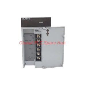
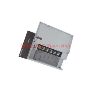
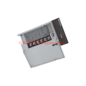
2MLR-DC42 Honeywell MasterLogic PLC Power Supply Module 5VDC Output
Manufacturer: Honeywell
Product No.: 2MLR-DC42
Condition: In stock
Product Type: Power Supply Module
Product Origin: USA
Payment: T/T, Western Union
Weight: 417g
Shipping port: Xiamen
Warranty: 12 months
Estimate delivery times: 12-26 days (International), 3-6 days (United States).
Return within 30 days of purchase. Duties & taxes are non-refundable.
Guaranteed Safe Checkout
Honeywell 2MLR-DC42 | MasterLogic PLC Power Supply Module
The Honeywell 2MLR-DC42 is a dedicated power supply module for industrial PLC control systems. It converts a 24 VDC input into a regulated 5 VDC output for compatible control hardware.
The module delivers up to 7.5 A output current and 37.5 W output power at 55°C. Its input range accommodates supply variations from 19.2 VDC to 28.8 VDC.
Built-in overcurrent protection helps protect the power output during abnormal load conditions. The integrated RUN contact provides a switching interface for external status monitoring. A front-panel LED indicates normal output voltage status.
01 | Electrical Performance and Power Conversion
The power conversion stage supplies regulated DC power to compatible PLC hardware. Its specified input range supports practical variations in industrial DC distribution systems.
| Manufacturer | Honeywell |
| Model | 2MLR-DC42 |
| Product Series | MasterLogic PLC |
| Product Type | Power Supply Module |
| Rated Input Voltage | 24 VDC |
| Input Voltage Range | 19.2–28.8 VDC |
| Inrush Current | 80 A peak or lower |
| Efficiency | 65% minimum |
| Output Voltage | 5 VDC ±2% |
| Rated Output Current | 7.5 A |
| Rated Output Power | 37.5 W at 55°C |
| Overcurrent Protection | 9.0–17.0 A |
| Instantaneous Interruption Tolerance | Within 20 ms |
| Voltage Status Indicator | LED indication for normal output voltage |
| Dimensions (W × H × D) | 55 × 95 × 110 mm |
| Weight | 417 g |
02 | Protection Architecture and Internal Safeguards
The 2MLR-DC42 integrates protective components to support stable operation under specified conditions.
- Input fuse protection: Built-in fuses protect the input circuit. Users cannot replace these fuses.
- AC fuse specification: 250 V / 3.15 A, time-lag type, UL approved.
- DC fuse specification: 125 V / 10 A, time-lag type, UL approved.
- Overcurrent protection: The specified protection range is 9.0 A to 17.0 A.
- Input interruption tolerance: Supports instantaneous interruptions within 20 ms.
- Output monitoring: The LED indicates normal output voltage status.
Protection thresholds do not represent recommended continuous operating currents. Engineers should follow the manufacturer's electrical specifications when evaluating abnormal load conditions.
03 | RUN Contact and External Status Monitoring
The module provides a RUN contact for external status signaling. This interface supports integration with supervisory circuits and external monitoring equipment.
| Contact Purpose | RUN contact |
| Rated Switching Voltage | 24 VDC |
| Rated Switching Current | 0.5 A |
| Minimum Switching Load | 5 VDC, 1 mA |
| OFF to ON Response | 10 ms maximum |
| ON to OFF Response | 12 ms maximum |
| Mechanical Life | 20 million operations or more |
| Electrical Life | 100,000 operations or more at rated switching current |
Engineers can use the RUN contact for external status supervision. Confirm the contact logic and wiring arrangement against the official connection diagram before integrating it into an interlock circuit.
04 | Wiring Requirements and Terminal Selection
Correct conductor selection helps maintain reliable electrical connections. The specified cable range supports common industrial control wiring practices.
- Supported cable size: 0.75–2 mm².
- Available terminal: RAV1.25-3.5.
- Available terminal: RAV2-3.5.
- Connection inspection: Check conductor insertion and terminal fastening.
- Wiring verification: Confirm polarity before applying DC input power.
Use suitable crimping tools for the selected terminal. Follow the manufacturer's recommended tightening torque and wiring diagram.
05 | Installation and Commissioning Procedure
A controlled commissioning process helps identify wiring errors before PLC operation.
- Inspect the module: Check the housing, terminals, and electrical interfaces.
- Verify input power: Confirm a nominal 24 VDC supply.
- Check voltage limits: Keep the input within 19.2–28.8 VDC.
- Confirm wiring: Check polarity and conductor specifications.
- Verify installation: Follow the designated MasterLogic mounting arrangement.
- Apply power: Energize the module after completing electrical checks.
- Check output: Measure the 5 VDC output using a suitable meter.
- Inspect status: Confirm the voltage indicator shows normal output status.
- Test RUN signaling: Verify external monitoring responds correctly.
Safety note: Isolate the power source before wiring or removing the module. Never attempt to replace its internal fuses. Follow the manufacturer's service instructions.
06 | Maintenance and Field Diagnostics
Regular electrical checks help identify developing power supply problems. Focus on input stability, output voltage, and connection integrity.
- Measure the 24 VDC input under normal operating load.
- Check the 5 VDC output against its ±2% tolerance.
- Inspect terminal connections for looseness or overheating.
- Monitor the output status LED during operation.
- Review the RUN contact response when external alarms occur.
- Check connected loads when overcurrent protection activates.
If the output becomes unstable, isolate the load and measure the supply independently. This approach helps distinguish module faults from downstream wiring or load problems.
07 | Selection and System Integration Considerations
Correct selection requires more than matching the input voltage. Engineers should evaluate output demand, load behavior, wiring, and monitoring requirements.
- Input compatibility: The available DC source must remain within the specified voltage range.
- Output capacity: Calculate the total 5 VDC load before selecting the supply.
- Power budget: Keep the continuous load within the 7.5 A and 37.5 W ratings.
- Inrush assessment: Consider the specified 80 A peak limit when evaluating upstream protection.
- Monitoring integration: Check RUN contact ratings against the connected circuit.
- Mechanical compatibility: Verify dimensions and mounting arrangements against the target PLC assembly.
Do not assume compatibility with every MasterLogic PLC configuration. Confirm the exact base, CPU, and power distribution requirements before ordering.
08 | Five Engineering FAQs
Q1: Why should engineers measure the 5 VDC output under actual operating load?
Power supply behavior can differ between unloaded and loaded conditions. A stable unloaded reading does not confirm sufficient current capacity. Measure the output during representative operation to identify voltage drops and load-related instability.
Q2: How should engineers evaluate the 80 A peak inrush current?
Consider the inrush characteristic when coordinating upstream DC protection and power distribution. Do not size protective devices using steady-state current alone. Check the manufacturer's startup characteristics and the upstream supply specifications.
Q3: What should be investigated if the output LED does not indicate normal voltage?
First, verify the input voltage and polarity. Next, inspect downstream wiring and connected loads. Check for overload conditions or short circuits. If the problem remains, isolate the module and arrange further technical inspection.
Q4: Can the RUN contact directly control a high-current field device?
The specified switching rating is 24 VDC at 0.5 A. This rating limits the permissible direct switching load. For higher-current applications, use an appropriately rated interposing relay or interface device.
Q5: When should engineers replace the complete module instead of troubleshooting the external circuit?
Consider module replacement when the input remains within specification but the output stays outside tolerance. First eliminate external short circuits, excessive loads, and loose connections. Since the internal fuses are not user-replaceable, do not attempt internal fuse repairs.
Tags
Q: Are these parts 100% original and new?
A: Yes. Every component is guaranteed to be 100% original, brand-new, and factory-sealed. We also provide a 12-month comprehensive warranty for your peace of mind.
Q: How fast is the shipping to my country?
A: For in-stock items, we offer same-day dispatch. International express shipping (DHL/FedEx/UPS) typically delivers within 3–5 business days worldwide.
Q: Can I get a formal quotation with shipping costs?
A: Absolutely. Our sales team is ready to provide a detailed Proforma Invoice (PI) including the most competitive shipping rates for your location.
Q: Do you offer discounts for bulk orders?
A: We provide volume-based pricing for large projects or multiple-item orders. Please contact us to get our Best Price Guarantee.
12-Month Comprehensive Warranty
Every part supplied by Global PLC Spare Hub is covered by a 12-month warranty from the date of invoice.
- Coverage: Functional defects and hardware failures under normal operating conditions.
- Commitment: We provide immediate repair, replacement, or a full refund for any verified defective components to minimize your operational downtime.
Returns & Exchange Policy
We offer a 30-day return policy to ensure you receive the exact part your system requires.
- Eligibility: Returns are accepted for uninstalled items in their original, factory-sealed packaging.
- RMA Process: Please contact our support team to obtain a Return Merchandise Authorization (RMA) number before shipping.
- Fast Processing: Refunds or exchanges are processed within 3–5 business days after the returned item passes our technical inspection.
Need Technical Assistance?Not sure if this part is compatible with your system? [Consult our Engineers] before purchasing to ensure 100% compatibility.
People Also Bought


