


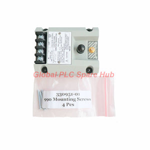

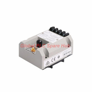
Bently Nevada 990-04-70-01-05 | 990 Vibration Transmitter
Manufacturer: Bently Nevada
Product No.: 990-04-70-01-05
Condition: In stock
Product Type: Vibration Transmitter
Product Origin: USA
Payment: T/T, Western Union
Weight: 430g
Shipping port: Xiamen
Warranty: 12 months
Estimate delivery times: 12-26 days (International), 3-6 days (United States).
Return within 30 days of purchase. Duties & taxes are non-refundable.
Guaranteed Safe Checkout
Product Overview
Bently Nevada 990-04-70-01-05 is a 990 Series Vibration Transmitter designed for continuous machinery vibration monitoring.
It accepts signals from one 3300 NSv Proximity Probe and its compatible extension cable. The transmitter converts shaft vibration measurements into a standard 4–20 mA DC output.
This two-wire configuration supports direct integration with PLC, DCS, and industrial monitoring systems. Maintenance teams can use the output for continuous vibration trending, alarm processing, and machinery condition assessment.
The 990 transmitter provides external zero and span adjustments. Its NOT OK signal defeat function also helps identify measurement-system faults.
Manufacturer: Bently Nevada
Model: 990-04-70-01-05
Product Series: 990 Vibration Transmitter
Country of Origin: Made in U.S.A.
Technical Specifications
| Parameter | Specification |
| Brand | Bently Nevada |
| Model | 990-04-70-01-05 |
| Product Type | 990 Vibration Transmitter |
| Measurement Input | One 3300 NSv Proximity Probe and extension cable |
| Full-Scale Measurement Range | 0–4 mils peak-to-peak (0–100 μm pp) |
| Output Signal | 4–20 mA DC, two-wire configuration |
| Frequency Response | 5 Hz to 6,000 Hz (+0, −3 dB) |
| Loop Accuracy | ±1.5% of specified full-scale range |
| Zero Adjustment | External adjustment |
| Span Adjustment | External adjustment |
| Probe Gap | 0.5–1.75 mm (20–55 mils) |
| Minimum Target Diameter | 9.5 mm (0.375 in) |
| Operating Supply Voltage | +12 to +35 VDC at transmitter terminals |
| Power Supply for Specified Hazardous-Area Configuration | 28 VDC |
| Maximum Loop Resistance | 1,000 Ω at 35 VDC, including cable |
| Current Limiting | 23 mA typical |
| NOT OK Output Response | Below 3.6 mA within 100 μs after a NOT OK condition |
| Signal Recovery | 2–3 seconds after the NOT OK condition clears |
| Proximitor Output Cable Distance | Maximum 3 m (10 ft) at the BNC connector |
| System Length Option | 7.0 m (23.0 ft) |
| Mounting Option | 35 mm DIN rail clips |
| Transmitter Weight | 0.43 kg (0.9 lb) |
| Country of Origin | U.S.A. |
Model Number Configuration
The ordering code identifies the measurement range, system length, mounting arrangement, and agency approval configuration.
| Code Segment | Configuration |
| 990 | 990 Series Vibration Transmitter |
| 04 | 0–4 mils pp (0–100 μm pp) full-scale range |
| 70 | 7.0 m (23.0 ft) system length |
| 01 | 35 mm DIN rail mounting clips |
| 05 | CSA Division 2, ATEX Zone 0, ATEX Zone 2, and ABS maritime approval configuration |
Complete Model: 990-04-70-01-05
Measurement Performance and Signal Characteristics
- Measurement Range: The 0–100 μm pp range supports shaft vibration monitoring within the selected full-scale configuration.
- Frequency Response: The 5 Hz–6 kHz bandwidth supports vibration measurements across a broad operating frequency range.
- Signal Accuracy: The loop accuracy is ±1.5% of the specified full-scale range.
- Output Resolution: The transmitter provides a continuous analog 4–20 mA signal. The manufacturer does not specify a digital resolution value.
- Linearity: The supplied specifications do not provide a separate linearity figure. Do not interpret loop accuracy as a standalone linearity specification.
- Sensitivity: The system uses the compatible 3300 NSv probe's incremental scale factor. The supplied model information does not state a separate transmitter sensitivity value.
- Fault Indication: The NOT OK function drives the output below 3.6 mA following a detected NOT OK condition.
- Signal Stability: External zero and span controls support field calibration and measurement adjustment.
Installation Guide
1. DIN Rail Mounting
- Install the transmitter using its specified 35 mm DIN rail clips.
- Choose a suitable control cabinet location with adequate access and ventilation.
- Secure the unit before connecting field wiring.
2. Probe Installation
- Use one compatible 3300 NSv Proximity Probe with its extension cable.
- Position the probe perpendicular to the target surface.
- Set the probe gap between 0.5 and 1.75 mm.
- Confirm the target diameter reaches at least 9.5 mm.
- Check the complete probe and extension cable configuration before commissioning.
3. Electrical Connections
- Connect the transmitter to a suitable DC power supply.
- Maintain an input voltage between +12 and +35 VDC at the transmitter terminals.
- Wire the 4–20 mA output into the receiving PLC or DCS analog input.
- Keep the total loop resistance within 1,000 Ω at 35 VDC.
- For the specified hazardous-area configuration, verify the required 28 V power supply arrangement.
4. Cable Routing
- Keep probe wiring away from high-voltage switching cables.
- Use suitable grounding and shielding practices for the installation.
- Observe the maximum 3 m cable distance for the Proximitor Sensor Output at the BNC connector.
Commissioning and Maintenance
Initial Commissioning
- Verify the complete probe, extension cable, and transmitter combination.
- Check the DC supply voltage at the transmitter terminals.
- Confirm the probe gap before applying operating conditions.
- Measure the loop current and verify the expected 4–20 mA response.
- Use the external zero and span controls to establish the required measurement range.
- Check the NOT OK response through an approved test procedure.
Routine Maintenance
- Inspect terminal connections for looseness or corrosion.
- Check cable insulation and connector condition during scheduled maintenance.
- Compare transmitter readings with independent vibration measurements when investigating abnormal values.
- Investigate output currents below 3.6 mA as potential NOT OK indications.
- Verify zero and span settings after probe replacement or maintenance.
Engineering Note: The NOT OK function provides a useful fault indication. However, technicians should inspect the entire measurement chain before replacing the transmitter.
Compatibility and System Integration
The Bently Nevada 990-04-70-01-05 requires a compatible 3300 NSv proximity measurement chain.
- Probe Compatibility: One 3300 NSv Proximity Probe.
- Extension Cable: Compatible 3300 NSv extension cable.
- Monitoring Input: PLC, DCS, or monitoring equipment with a compatible 4–20 mA analog input.
- Power Supply: +12 to +35 VDC at the transmitter terminals.
- Loop Design: The complete circuit must remain within the specified 1,000 Ω maximum loop resistance at 35 VDC.
Important Selection Consideration: The 7.0 m system length represents the specified probe measurement-chain configuration. Verify the actual probe and extension cable combination before ordering.
Do not substitute a different probe family without confirming electrical compatibility, scale factor, system length, and calibration requirements.
Certifications and Environmental Considerations
- CSA: Division 2 hazardous-area approval.
- ATEX: Zone 0 and Zone 2 approval configuration.
- ABS: Includes American Bureau of Shipping maritime approval.
- Origin: Made in U.S.A.
Environmental Data: The supplied specifications do not state the operating temperature range, humidity limits, ingress protection rating, or vibration resistance of the transmitter enclosure. Confirm these values against the applicable manufacturer documentation before installation.
For hazardous-area applications, verify the complete installation against the equipment certification, wiring requirements, and applicable site regulations.
Packaging and Delivery
- 1 × Bently Nevada 990-04-70-01-05 Vibration Transmitter
- 35 mm DIN rail mounting configuration
- Protective packaging suitable for transportation
Note: Probe, extension cable, power supply, and additional accessories are not included unless the order explicitly specifies them.
Global PLC Spare HUB's Insight
From a machinery protection engineering perspective, the 990-04-70-01-05 serves as a signal conditioning and transmission device for proximity-based vibration monitoring.
Its 4–20 mA output simplifies integration with conventional industrial control systems. This arrangement allows operators to monitor vibration levels without requiring a dedicated proximity monitoring rack.
The 0–100 μm pp measurement range suits applications that require a defined vibration measurement span. The 5 Hz–6 kHz frequency response supports monitoring across multiple machinery operating conditions.
One important commissioning detail concerns the NOT OK output. A current below 3.6 mA indicates a measurement-system fault condition rather than an ordinary vibration reading.
Engineers should therefore configure PLC or DCS logic to distinguish measurement faults from normal process alarms. This approach improves diagnostic reliability and reduces incorrect vibration assessments.
Before purchasing, confirm the probe family, system length, mounting code, and hazardous-area approval requirements. These details directly affect installation compatibility and commissioning results.
Frequently Asked Questions (FAQ)
Q1: What does the Bently Nevada 990-04-70-01-05 measure?
It measures shaft vibration through a compatible 3300 NSv Proximity Probe. It converts the measurement into a 4–20 mA analog output.
Q2: What does the 04 code represent?
The 04 code specifies a full-scale measurement range of 0–4 mils peak-to-peak, equivalent to 0–100 μm pp.
Q3: Can this transmitter connect directly to a PLC or DCS?
Yes. Its two-wire 4–20 mA output supports compatible analog input channels. Check the receiving channel's loop power and resistance requirements.
Q4: What does an output below 3.6 mA indicate?
It indicates a NOT OK condition. The transmitter drives the output below 3.6 mA within 100 μs after detecting the condition.
Q5: Why does the transmitter require a specific probe gap?
The probe gap affects the measurement operating point. Maintain 0.5–1.75 mm to support the specified full-scale measurement range.
Q6: Does the 7.0 m system length mean the BNC cable can extend 7 meters?
No. The 7.0 m system length identifies the specified probe measurement-chain configuration. The Proximitor Sensor Output cable distance has a separate 3 m maximum specification.
Q7: What should engineers check when the output remains below 3.6 mA?
First, inspect the probe, extension cable, power supply, and field wiring. Then check the probe gap and system compatibility. Replace components only after identifying the fault source.
Q8: How should buyers select the correct 990 transmitter?
Compare the required full-scale range, probe family, system length, mounting arrangement, and certification requirements. Also confirm the receiving system's 4–20 mA input compatibility.
Q9: Is this model suitable for hazardous-area applications?
Its specified approval configuration includes CSA Division 2, ATEX Zone 0, ATEX Zone 2, and ABS maritime approval. Verify the applicable certificate and installation conditions for the intended location.
Q10: What information should buyers provide when requesting a quotation?
Provide the complete model number, required quantity, application, destination country, and any probe or cable requirements. This information helps verify configuration compatibility and quotation accuracy.
Ordering Information
Product: Bently Nevada 990 Vibration Transmitter
Model: 990-04-70-01-05
Global PLC Spare HUB supplies industrial automation components for machinery monitoring, process control, and equipment maintenance applications.
Contact our sales team for product pricing, availability, configuration verification, and delivery arrangements.

Tags
Q: Are these parts 100% original and new?
A: Yes. Every component is guaranteed to be 100% original, brand-new, and factory-sealed. We also provide a 12-month comprehensive warranty for your peace of mind.
Q: How fast is the shipping to my country?
A: For in-stock items, we offer same-day dispatch. International express shipping (DHL/FedEx/UPS) typically delivers within 3–5 business days worldwide.
Q: Can I get a formal quotation with shipping costs?
A: Absolutely. Our sales team is ready to provide a detailed Proforma Invoice (PI) including the most competitive shipping rates for your location.
Q: Do you offer discounts for bulk orders?
A: We provide volume-based pricing for large projects or multiple-item orders. Please contact us to get our Best Price Guarantee.
12-Month Comprehensive Warranty
Every part supplied by Global PLC Spare Hub is covered by a 12-month warranty from the date of invoice.
- Coverage: Functional defects and hardware failures under normal operating conditions.
- Commitment: We provide immediate repair, replacement, or a full refund for any verified defective components to minimize your operational downtime.
Returns & Exchange Policy
We offer a 30-day return policy to ensure you receive the exact part your system requires.
- Eligibility: Returns are accepted for uninstalled items in their original, factory-sealed packaging.
- RMA Process: Please contact our support team to obtain a Return Merchandise Authorization (RMA) number before shipping.
- Fast Processing: Refunds or exchanges are processed within 3–5 business days after the returned item passes our technical inspection.
Need Technical Assistance?Not sure if this part is compatible with your system? [Consult our Engineers] before purchasing to ensure 100% compatibility.
People Also Bought


