


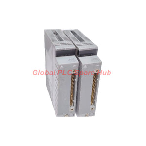
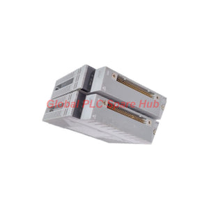
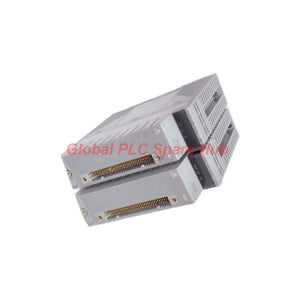
AAR145-S50 Yokogawa RTD/POT Input Module | 16-Channel
Manufacturer: Yokogawa
Product No.: AAR145-S50
Condition: In stock
Product Type: RTD/POT Input Module
Product Origin: SG
Payment: T/T, Western Union
Weight: 500g
Shipping port: Xiamen
Warranty: 12 months
Estimate delivery times: 12-26 days (International), 3-6 days (United States).
Return within 30 days of purchase. Duties & taxes are non-refundable.
Guaranteed Safe Checkout
01 | Product Profile – Resistance Signal Acquisition
The Yokogawa AAR145-S50 is a 16-channel RTD/POT Input Module designed for industrial measurement and control applications. It acquires resistance signals from resistance temperature detectors (RTDs) and potentiometers (POTs). Its 16 isolated input channels support individual RTD or POT signal selection. The module accepts three-wire Pt100 RTD signals and potentiometer resistance signals. It provides dedicated measurement functions for temperature monitoring and resistance-based position feedback. With individual channel selection, engineers can configure different input signal types within one module. This arrangement offers flexibility when integrating temperature sensors and position measurement devices. The AAR145-S50 is suitable for distributed measurement systems requiring multiple resistance input points. Its dedicated cable connection supports integration with compatible Yokogawa terminal board configurations. Primary Engineering Functions
- Acquires signals from 16 independent RTD/POT input channels.
- Supports three-wire Pt100 temperature sensors.
- Measures potentiometer resistance from 100 Ω to 10 kΩ.
- Allows individual RTD/POT selection for each channel.
- Provides specified input-to-system and channel-to-channel withstand voltage.
- Updates measurement data every 1 second.
02 | Ordering Code and Configuration Breakdown
The complete model number identifies the module type and ordering configuration.
| Code | Classification | Technical Description |
|---|---|---|
| AAR145 | Model | 16-channel RTD/POT Input Module with isolated channels |
| 5 | Suffix Code | Without explosion protection |
| 0 | Suffix Code | Basic type |
Complete Ordering Reference: AAR145-S50
- AAR145: Identifies the RTD/POT input module.
- S: Ordering designation included in the supplied product reference.
- 5: Specifies the version without explosion protection.
- 0: Specifies the basic type.
Configuration Selection Note: The supplied suffix description defines codes 5 and 0. Confirm the meaning of the S designation against the applicable Yokogawa ordering specification before placing an order.
03 | Technical Data and Measurement Performance
| Parameter | Specification |
|---|---|
| Manufacturer | Yokogawa |
| Model | AAR145-S50 |
| Base Model | AAR145 |
| Product Type | RTD/POT Input Module |
| Input Channels | 16 isolated channels |
| Input Selection | Individual RTD/POT selection for CH1–CH16 |
| RTD Standard | JIS C1604:1997; IEC 751:1995 |
| RTD Sensor | Pt100, three-wire type |
| POT Resistance Range | 100 Ω to 10 kΩ |
| POT Span Resistance | 50% or greater of total resistance |
| Allowable Input Voltage | ±5 V |
| RTD Accuracy | ±150 mΩ |
| POT Accuracy | ±0.2% / FS |
| RTD Measurement Current | 1 mA |
| Maximum Signal Source and Wiring Resistance | 150 Ω or less, per wire |
| Data Update Period | 1 second |
| RTD Temperature Drift | ±0.3 Ω / 10 °C |
| POT Temperature Drift | ±0.4% / 10 °C |
| Allowable Input-to-System Voltage | 500 V AC, 1 minute; 1500 V AC for a single card |
| Input-to-Input Withstand Voltage | 200 V AC, 1 minute |
| Maximum Current Consumption | 350 mA at 5 V DC |
| External Connection | Dedicated cable, KS8 / AKB335 |
| Weight | Approximately 0.3 kg |
| Explosion Protection | Not provided |
04 | Input Measurement Architecture
A. RTD Temperature Measurement The RTD input function supports three-wire Pt100 sensors. It measures resistance changes associated with process temperature variations. Key characteristics:
- Sensor type: Pt100.
- Connection: Three-wire configuration.
- Supported standards: JIS C1604:1997 and IEC 751:1995.
- Measurement current: 1 mA.
- Specified accuracy: ±150 mΩ.
- Temperature drift: ±0.3 Ω per 10 °C.
Three-wire wiring helps compensate for lead resistance effects. Engineers should maintain consistent wire connections and check cable resistance during installation. B. Potentiometer Resistance Measurement The POT input function measures resistance changes from connected potentiometers. Key characteristics:
- Total resistance: 100 Ω to 10 kΩ.
- Span resistance: At least 50% of total resistance.
- Specified accuracy: ±0.2% of full scale.
- Temperature drift: ±0.4% per 10 °C.
This function supports position feedback from compatible mechanical adjustment and displacement devices. For example, a potentiometer connected to a valve position mechanism can provide resistance-based feedback. The control system can use this signal to monitor the actuator's operating position. C. Individual Channel Selection Each channel from CH1 to CH16 supports individual RTD or POT selection. This arrangement allows engineers to combine different resistance measurement points within one input module. It reduces the need to allocate separate modules for every sensor type.
05 | Electrical Isolation and Signal Integrity
The module provides specified withstand voltage between input and system circuits. It also provides withstand voltage between input channels.
| Isolation Test | Withstand Voltage | Duration |
|---|---|---|
| Input to System | 500 V AC | 1 minute |
| Single Card Input to System | 1500 V AC | 1 minute |
| Between Input Channels | 200 V AC | 1 minute |
These ratings describe electrical withstand performance. They do not represent continuous operating voltage ratings. Engineers should also separate low-level sensor wiring from high-power motor cables. Proper cable routing helps reduce unwanted electrical interference.
06 | Reference Junction Compensation and Terminal Board Conditions
The supplied technical data includes reference junction compensation accuracy associated with the AET4D terminal board. The specified accuracy varies with terminal board ambient temperature. AET4D Terminal Board Only
| Ambient Temperature | Compensation Accuracy |
|---|---|
| -20 to 0 °C | ±1.5 °C |
| 0 to 30 °C | ±1.0 °C |
| 30 to 70 °C | ±1.5 °C |
Installation in Standard Cabinet
| Ambient Temperature | Compensation Accuracy |
|---|---|
| 0 to 30 °C | ±1.0 °C |
| 30 to 50 °C | ±1.5 °C |
Engineering Note: These figures relate to the supplied terminal board compensation data. They should not be interpreted as additional AAR145 RTD measurement accuracy specifications. Confirm their applicability to the actual terminal board and measurement configuration.
07 | Installation and Wiring Recommendations
Correct sensor wiring directly affects resistance measurement accuracy. Engineers should verify the complete signal path before commissioning. Installation Preparation
- Confirm the module reference: AAR145-S50.
- Verify the compatible Yokogawa I/O system and mounting arrangement.
- Confirm the required terminal board and dedicated cable.
- Check the sensor type and resistance range.
- Inspect the cabinet environment and grounding arrangement.
RTD Wiring Checks
- Use compatible three-wire Pt100 sensors.
- Verify the terminal assignments before connecting the sensor.
- Check individual wire continuity.
- Measure wiring resistance and confirm the specified limits.
- Keep sensor cables away from high-current wiring.
POT Wiring Checks
- Confirm the potentiometer's total resistance.
- Verify that the selected span meets the 50% minimum requirement.
- Check resistance variation across the mechanical travel range.
- Inspect the wiper connection for intermittent contact.
- Confirm the selected channel uses POT input configuration.
Connection Accessories The supplied specification identifies dedicated KS8/AKB335 cable connections. Confirm the required cable reference and terminal board arrangement before ordering accessories.
08 | Commissioning and Field Diagnostics
The AAR145-S50 supports resistance-based process measurement. Accurate commissioning requires checking the sensor, wiring, channel configuration, and terminal board together. Diagnostic Case 1: RTD Temperature Readings Are Unstable Possible causes include loose terminals, inconsistent wire resistance, damaged sensor leads, or electrical interference. Recommended checks:
- Inspect all three RTD conductors.
- Measure sensor resistance with a suitable instrument.
- Check individual lead resistance.
- Inspect cable shielding and routing.
- Compare readings with a known reference instrument.
Diagnostic Case 2: POT Position Feedback Does Not Match Mechanical Travel Possible causes include incorrect total resistance, insufficient span resistance, or mechanical wear. Recommended checks:
- Measure the potentiometer's total resistance.
- Check the resistance change across the complete travel range.
- Inspect the wiper for unstable contact.
- Verify the channel's POT configuration.
- Compare electrical feedback with actual actuator position.
Diagnostic Case 3: One Channel Shows an Abnormal Reading First compare the affected channel with other configured channels. Inspect sensor wiring and terminal connections. Check the individual input selection before suspecting module hardware. Diagnostic Case 4: Measurement Accuracy Changes with Cabinet Temperature Check the terminal board ambient temperature. Compare the installation conditions with the AET4D compensation specifications. Also inspect sensor wiring and module temperature drift. Maintenance Recommendations
- Inspect sensor terminals during scheduled shutdowns.
- Record RTD resistance and temperature readings.
- Check potentiometer travel and wiper stability.
- Inspect dedicated cable connections.
- Compare critical measurements with calibrated reference instruments.
- Record channel configuration changes for future troubleshooting.
09 | Compatible Equipment and Industrial Applications
The module is designed for compatible Yokogawa distributed I/O configurations. Its measurement functions suit equipment that requires temperature or resistance-based position feedback. 1. Chemical and Petrochemical Processing Suitable measurement points include:
- Process vessel temperature monitoring.
- Heat exchanger temperature measurement.
- Reactor temperature monitoring.
- Auxiliary equipment temperature feedback.
2. Oil and Gas Production RTD channels can monitor equipment temperatures in compatible control systems. POT channels can collect position feedback from suitable mechanical devices. 3. Power Generation Equipment Potential measurement applications include:
- Auxiliary equipment temperature monitoring.
- Cooling system temperature measurement.
- Mechanical position feedback.
- Process equipment condition monitoring.
4. Industrial Valve and Actuator Systems POT inputs can monitor resistance changes from compatible position transmitters. Engineers can compare the feedback signal with commanded actuator movement. 5. Manufacturing and Process Machinery The module can collect temperature and mechanical position signals from distributed equipment. Individual channel selection supports mixed RTD/POT measurement requirements.
10 | Global PLC Spare HUB's Insight
The main engineering advantage of the AAR145-S50 is its ability to combine RTD and POT measurements across 16 isolated channels. However, mixed signal capability does not eliminate the need for careful channel planning. Each input must match its connected sensor type and wiring arrangement. Field Example: Heat Exchanger and Valve Monitoring Consider a chemical processing unit with multiple heat exchangers and control valves. The maintenance team needs to monitor several Pt100 temperature sensors. It also needs resistance-based position feedback from compatible valve mechanisms. Engineers can configure individual AAR145 channels for the required RTD or POT signals. They should then verify each sensor's resistance range and wiring arrangement. During commissioning, one temperature channel may show a reading different from the reference instrument. A practical troubleshooting sequence starts with the three-wire connection and lead resistance. For a valve feedback channel, an inconsistent position reading requires a different inspection approach. Engineers should check potentiometer travel, total resistance, and wiper contact. Our Engineering Recommendation: Do not evaluate this module only by its 16-channel capacity. Check the RTD accuracy, POT full-scale accuracy, wiring resistance limits, temperature drift, and terminal board configuration. This approach helps prevent measurement errors and reduces unnecessary module replacement.
11 | Procurement, Warranty and Shipping
Product Identification
- Manufacturer: Yokogawa
- Model: AAR145-S50
- Product: RTD/POT Input Module
- Input Capacity: 16 isolated channels
Warranty Policy Global PLC Spare HUB provides a 12-month warranty for the supplied product, subject to applicable sales terms. International Shipping Available shipping methods include:
- FedEx
- UPS
- DHL
We can arrange shipping according to the confirmed order and destination. Contact our sales team to confirm availability, pricing, and accessory requirements.
12 | Frequently Asked Questions
Q1. How should engineers evaluate the measurement error when using long RTD cables? Cable resistance is an important factor in three-wire RTD measurements. The specified signal source and wiring resistance must remain within the stated limits. Engineers should measure each conductor and check connection consistency before calibrating the measurement loop. Q2. What happens if a potentiometer provides less than 50% span resistance? The supplied specification requires a span resistance of at least 50% of total resistance. A smaller span does not meet the specified input requirement. Select a suitable potentiometer or review the mechanical measurement arrangement. Q3. Can all 16 channels measure the same signal type? Yes. Individual channel selection allows engineers to configure RTD or POT inputs separately. All 16 channels can therefore be assigned according to the actual sensor arrangement, subject to system configuration requirements. Q4. How should maintenance teams verify the RTD measurement accuracy? Use a calibrated resistance simulator or suitable reference instrument. Compare the module reading against known resistance values. Record the results across representative measurement points and inspect the wiring before adjusting the system. Q5. What information should buyers provide when selecting an AAR145 replacement? Provide the complete model number, existing I/O configuration, terminal board reference, cable type, and required input signal types. Also confirm whether the application requires RTD, POT, or mixed-channel operation. These details help prevent accessory and compatibility mismatches.
13 | Request a Quote – Yokogawa AAR145-S50
Looking for a Yokogawa AAR145-S50 16-Channel RTD/POT Input Module? Global PLC Spare HUB supports industrial automation spare parts sourcing for process control and distributed I/O applications. Send us your complete model number and required quantity. Our team can assist with product verification, quotation, and international shipping arrangements.

Tags
Q: Are these parts 100% original and new?
A: Yes. Every component is guaranteed to be 100% original, brand-new, and factory-sealed. We also provide a 12-month comprehensive warranty for your peace of mind.
Q: How fast is the shipping to my country?
A: For in-stock items, we offer same-day dispatch. International express shipping (DHL/FedEx/UPS) typically delivers within 3–5 business days worldwide.
Q: Can I get a formal quotation with shipping costs?
A: Absolutely. Our sales team is ready to provide a detailed Proforma Invoice (PI) including the most competitive shipping rates for your location.
Q: Do you offer discounts for bulk orders?
A: We provide volume-based pricing for large projects or multiple-item orders. Please contact us to get our Best Price Guarantee.
12-Month Comprehensive Warranty
Every part supplied by Global PLC Spare Hub is covered by a 12-month warranty from the date of invoice.
- Coverage: Functional defects and hardware failures under normal operating conditions.
- Commitment: We provide immediate repair, replacement, or a full refund for any verified defective components to minimize your operational downtime.
Returns & Exchange Policy
We offer a 30-day return policy to ensure you receive the exact part your system requires.
- Eligibility: Returns are accepted for uninstalled items in their original, factory-sealed packaging.
- RMA Process: Please contact our support team to obtain a Return Merchandise Authorization (RMA) number before shipping.
- Fast Processing: Refunds or exchanges are processed within 3–5 business days after the returned item passes our technical inspection.
Need Technical Assistance?Not sure if this part is compatible with your system? [Consult our Engineers] before purchasing to ensure 100% compatibility.
People Also Bought


