


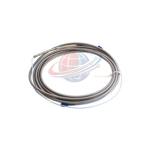
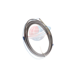
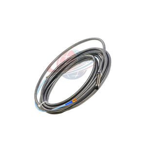
Bently Nevada 330130-085-03-05 3300 XL Extension Cable
Manufacturer: Bently Nevada
Product No.: 330130-085-03-05
Condition: In stock
Product Type: Extension Cable
Product Origin: USA
Payment: T/T, Western Union
Weight: 618g
Shipping port: Xiamen
Warranty: 12 months
Estimate delivery times: 12-26 days (International), 3-6 days (United States).
Return within 30 days of purchase. Duties & taxes are non-refundable.
Guaranteed Safe Checkout
Product Overview
Bently Nevada 330130-085-03-05 is an armored extension cable from the 3300 XL 8 mm Proximity Transducer System. It connects a compatible proximity probe to its Proximitor Sensor. The cable maintains signal transmission between these components in rotating machinery monitoring applications.
This configuration provides an 8.5-meter (27.9-foot) cable length, armored construction, and a connector protector. Its mechanical protection supports installations that require additional cable protection around industrial machinery.
The 3300 XL extension cable supports shaft displacement measurement in compressors, turbines, pumps, and other rotating equipment. Its electrical characteristics help maintain signal integrity within a correctly configured transducer system.
The 3300 XL design incorporates several connection improvements. Its patented TipLoc molding method strengthens the probe tip-to-body connection. The CableLoc design provides 330 N (75 lbf) pull strength between the probe cable and probe tip.
Technical Specifications
| Parameter | Specification |
| Manufacturer | Bently Nevada |
| Model | 330130-085-03-05 |
| Product Series | 3300 XL |
| Product Type | Proximity Probe Extension Cable |
| Compatible System | 3300 XL 8 mm Proximity Transducer System |
| Cable Length | 8.5 m (27.9 ft) |
| Cable Configuration | Armored cable |
| Connector Protection | Connector protector |
| Approval Option | 05 – CSA, ATEX, IECEx |
| Country of Manufacture | USA |
| Typical Armored Cable Weight | 103 g/m (1.5 oz/ft) |
| Total Armored Cable Weight | Approximately 0.875 kg |
| Typical Unarmored Cable Weight | 34 g/m (0.4 oz/ft) |
| Unarmored Cable Weight | Approximately 0.289 kg |
| Extension Cable Capacitance | 69.9 pF/m (21.3 pF/ft), typical |
| Center Conductor Resistance | 1.87 ± 0.28 Ω |
| Outer Conductor Resistance | 0.56 ± 0.11 Ω |
| Output Resistance | 50 Ω |
| CableLoc Pull Strength | 330 N (75 lbf), probe cable-to-tip connection |
Electrical Performance and Measurement Characteristics
The following electrical parameters describe the compatible 3300 XL 8 mm transducer system. They do not represent independent extension cable output specifications.
| Performance Parameter | Specification |
| System Supply Voltage | -17.5 to -26 Vdc |
| Supply Voltage with Barriers | -23 to -26 Vdc |
| Maximum Current Consumption | 12 mA |
| Voltage Sensitivity | Less than 2 mV output change per 1 V input change |
| System Linear Range | 2 mm (80 mils) |
| Linear Operating Region | Approximately 0.25–2.3 mm (10–90 mils) |
| Corresponding Output Range | Approximately -1 to -17 Vdc |
| Standard Test Gap | 1.27 mm (50 mils) |
| Frequency Response | Depends on the complete transducer configuration and field wiring |
| Resolution | No separate numerical value specified |
| Linearity Accuracy | System linearity percentage not specified in the supplied data |
| Operating Temperature | Confirm against the applicable cable and system documentation |
| Reference Test Temperature | +18°C to +27°C (+64°F to +80°F) |
| Maximum Reference Test Altitude | 2,000 m |
Important Electrical Considerations:
- The system requires a negative DC power supply within the specified voltage range.
- Barrier installations require -23 to -26 Vdc.
- Supply voltages more positive than -23.5 Vdc can reduce the available linear range.
- The system specifies a 50 Ω output resistance.
- The extension cable contributes 69.9 pF/m typical capacitance to the complete signal path.
- Frequency response depends on cable configuration and total field wiring length.
DC Resistance and Cable Characteristics
The 8.5-meter extension cable has defined resistance values for both conductors. These values help technicians evaluate cable continuity and electrical condition.
| Measurement Item | Resistance |
| Center Conductor to Center Conductor (RCORE) | 1.87 ± 0.28 Ω |
| Outer Conductor to Outer Conductor (RJACKET) | 0.56 ± 0.11 Ω |
Measure both conductor paths during cable inspection. Compare actual readings with the specified resistance ranges. Unexpected resistance changes may indicate connection problems or cable damage.
Environmental Resistance and Signal Protection
The 3300 XL extension cable supports industrial machinery monitoring installations. Its armored construction provides additional mechanical protection around the cable.
- Mechanical Protection: The armored construction helps protect the cable against external mechanical contact.
- Connector Protection: The specified connector protector helps protect the probe-to-cable connection.
- Humidity Performance: The complete system exhibits less than 3% Average Scale Factor change after 56 days at 93% relative humidity.
- Humidity Test Standard: IEC 68-2-3.
- Signal Integrity: Correct cable selection and routing help maintain the electrical characteristics of the transducer system.
- Oil Exposure: Avoid relying on silicone tape at probe-to-extension connections exposed to turbine oil.
Environmental Qualification Note: The humidity result describes the specified transducer system test. It does not establish an independent IP rating or universal chemical compatibility.
Installation Guidelines
Correct cable selection and installation directly affect proximity measurement performance. Follow these engineering recommendations during installation.
- Verify Cable Identification: Confirm model 330130-085-03-05 before connecting the assembly.
- Check Cable Length: Confirm the 8.5-meter extension length matches the system configuration.
- Inspect the Armor: Check for crushing, sharp bends, or visible mechanical damage.
- Inspect the Connectors: Examine the connector protector and electrical contact surfaces.
- Connect the Probe: Match the extension cable connector with the compatible 3300 XL 8 mm probe.
- Connect the Proximitor: Verify the opposite connection against the Proximitor Sensor requirements.
- Secure the Cable Route: Avoid excessive tension, sharp edges, and unnecessary mechanical stress.
- Verify Total System Length: Add the probe length and extension cable length. Confirm that their combined length matches the Proximitor Sensor configuration.
- Complete Electrical Testing: Check conductor continuity and resistance before commissioning.
Critical Configuration Rule: The combined probe and extension cable length must equal the specified Proximitor Sensor total length. An incorrect combination can cause measurement errors or prevent proper system operation.
Field Wiring and Commissioning
| Wiring Parameter | Requirement |
| Conductor Size | 0.2–1.5 mm² (16–24 AWG) |
| Recommended Field Cable | Three-conductor shielded triad cable |
| Field Wiring Material | Tinned field wiring recommended |
| Maximum Field Wiring Length | 305 m (1,000 ft) |
| Signal Destination | 3300 XL Proximitor Sensor to machinery monitor |
The 305-meter limit applies to field wiring between the Proximitor Sensor and monitor. It does not replace the specified 8.5-meter extension cable length.
During commissioning, technicians should perform these checks:
- Confirm the probe and extension cable form the correct system combination.
- Measure center conductor resistance and outer conductor resistance.
- Check connector engagement and cable continuity.
- Verify the Proximitor Sensor supply voltage.
- Confirm stable output signals at the monitoring system.
- Review signal behavior across the required machinery operating range.
Compatibility and System Integration
The 330130-085-03-05 belongs to the Bently Nevada 3300 XL 8 mm system. Engineers should verify all connected components before installation.
- Probe Compatibility: Use a compatible 3300 XL 8 mm proximity probe.
- Proximitor Compatibility: Verify the corresponding 3300 XL Proximitor Sensor configuration.
- Extension Cable Length: Include the 8.5-meter cable when calculating total system length.
- Connector Configuration: Confirm the connector protector and mating connector arrangement.
- Monitor Compatibility: Check the complete transducer system against the machinery monitor requirements.
- Target Material: Published system accuracy and interchangeability specifications use an AISI 4140 steel target.
The published system accuracy specifications do not automatically apply to alternative target materials. Confirm calibration requirements when the installation uses a different shaft material.
Certification and Approval Information
The ordering code identifies Approval Option 05. This configuration specifies the following approval standards:
- CSA
- ATEX
- IECEx
Verify the product nameplate and applicable approval documents before hazardous-area installation. Confirm the certificate scope, equipment group, temperature class, and installation requirements. Do not assume every installation configuration shares identical approval conditions.
Maintenance and Troubleshooting
Regular inspection helps maintain stable electrical connections and reliable machinery monitoring signals.
- High Conductor Resistance: Inspect connector contacts, cable continuity, and possible conductor damage.
- Unstable Measurement Signals: Check connector engagement, cable routing, grounding, and shielding.
- Intermittent Signal Loss: Inspect the cable for mechanical damage and loose connections.
- Incorrect System Calibration: Verify the combined probe and extension cable length.
- Abnormal High-Frequency Response: Review field wiring length and system frequency response.
- Connector Contamination: Inspect contact surfaces and replace damaged connection components.
- Oil Exposure: Inspect the probe-to-extension connection and avoid silicone tape where turbine oil exposure occurs.
Record the initial resistance measurements during commissioning. Maintain these readings as reference values for future inspections. Compare subsequent results to identify cable deterioration or connection changes.
Global PLC Spare HUB's Insight
Extension cable selection requires more than matching the nominal cable length. Engineers must also consider armor construction, connector protection, approval requirements, and total transducer system length.
For turbine and compressor installations, the armored configuration offers an additional mechanical protection layer. The connector protector also provides a defined connection protection arrangement. However, engineers should assess the actual installation environment before selecting protective accessories.
One frequent configuration issue involves the combined probe and extension cable length. The total must match the Proximitor Sensor configuration. A cable with the correct individual length may still create an incompatible system when paired with the wrong probe.
Another important consideration involves turbine oil exposure. Bently Nevada includes silicone tape with 3300 XL extension cables as an alternative to connector protectors. However, silicone tape is not recommended where turbine oil can contact the probe-to-extension cable connection.
For maintenance teams, recording conductor resistance provides a useful diagnostic reference. Compare the center conductor and outer conductor measurements during periodic inspections. This practice helps identify electrical changes before they affect machinery monitoring performance.
Model Selection and Technical Comparison
Engineers may also consider the following alternative when selecting a 3300 XL extension cable.
| Selection Criteria | 330130-085-03-05 | 330130-085-11-05 |
| Manufacturer | Bently Nevada | Bently Nevada |
| Product Series | 3300 XL | 3300 XL |
| Cable Length | 8.5 m | 8.5 m, based on model code |
| Configuration | Armored cable | Confirm against product documentation |
| Connector Arrangement | Connector protector | Verify suffix configuration |
| Approval Option | 05 – CSA, ATEX, IECEx | 05 – CSA, ATEX, IECEx |
| Selection Priority | Additional mechanical cable protection | Confirm cable construction and connector requirements |
| Product Reference | Current product | 330130-085-11-05 Bently Nevada Extension Cable |
Technical Selection Recommendations:
- Choose 330130-085-03-05 when the installation requires an armored extension cable and connector protector.
- Consider 330130-085-11-05 when evaluating the alternative shielded cable configuration. Confirm its detailed construction and connector arrangement before ordering.
- For hazardous-area installations: Verify the required CSA, ATEX, and IECEx documentation for the exact product configuration.
- For replacement projects: Match the existing cable length, probe interface, Proximitor Sensor, and approval requirements.
- For system upgrades: Check the complete transducer chain rather than comparing cable model numbers alone.
Our Recommendation: Select the 330130-085-03-05 when armored construction and connector protection match the installation requirements. Consider the alternative only after confirming its exact suffix definition and mechanical configuration. Do not assume that two cables with identical lengths have interchangeable connector or armor arrangements.
Packaging and Shipping Information
- 1 × Bently Nevada 330130-085-03-05 Armored Extension Cable.
- Specified connector protector configuration.
- Silicone tape supplied with the 3300 XL extension cable as an alternative connection protection material.
- Standard product packaging for transportation protection.
Confirm the final accessory contents against the sales quotation. Proximity probes, Proximitor Sensors, and additional field wiring are not included unless specifically listed.
Global PLC Spare HUB supports industrial automation spare-part sourcing. We provide a 12-month warranty and arrange shipments through FedEx, UPS, and DHL. Contact our sales team for current availability, pricing, and shipping arrangements. Typical dispatch arrangements are 24–48 hours, subject to stock and order confirmation.
Frequently Asked Questions (FAQ)
Q1: What is the primary function of the Bently Nevada 330130-085-03-05?
This cable connects a compatible 3300 XL 8 mm proximity probe to its Proximitor Sensor. It carries the measurement signal through the configured transducer system.
Q2: What does the 085 suffix represent?
The 085 cable length option specifies 8.5 meters (27.9 feet). This length must match the total system configuration requirements.
Q3: What is the difference between armored and unarmored extension cables?
Armored cables provide additional mechanical protection around the cable. Unarmored cables offer a lighter construction. Choose according to cable routing, installation exposure, and mechanical protection requirements.
Q4: Can technicians use silicone tape instead of the connector protector?
Yes. Each 3300 XL extension cable includes silicone tape as an alternative. However, Bently Nevada does not recommend this approach where turbine oil can expose the probe-to-extension connection.
Q5: How should technicians verify extension cable resistance?
Measure the center conductor and outer conductor separately. For the 8.5-meter cable, compare the readings with 1.87 ± 0.28 Ω and 0.56 ± 0.11 Ω, respectively.
Q6: Can this extension cable connect directly to a machinery monitor?
No. The cable connects the proximity probe and Proximitor Sensor. The Proximitor Sensor provides the interface to the machinery monitoring system.
Q7: Why must engineers calculate the combined probe and extension cable length?
The combined length must match the Proximitor Sensor total length. Incorrect length combinations can affect system compatibility and measurement performance. Always verify the complete configuration before installation.
Q8: What should maintenance engineers check when vibration readings become unstable?
First, inspect both cable connections and the armored section. Then measure conductor resistance and check cable routing. Finally, verify the Proximitor Sensor supply and complete signal chain.
Q9: How should buyers choose between 330130-085-03-05 and 330130-085-11-05?
Start with the existing cable construction and connector arrangement. The 330130-085-03-05 specifies armored construction with a connector protector. For the 330130-085-11-05, confirm its exact suffix configuration and mechanical details before substitution.
Q10: What information should buyers provide when requesting a quotation?
Provide the complete model number, required quantity, existing probe model, Proximitor Sensor model, and cable length. Include connector photographs and hazardous-area approval requirements when available.
Request a Quote for Bently Nevada 330130-085-03-05
Looking for a Bently Nevada 3300 XL Armored Extension Cable? Contact Global PLC Spare HUB for pricing, availability, and technical selection assistance.
Send us your complete model number and system configuration. Our team can help verify cable specifications and replacement compatibility before ordering.

Tags
Q: Are these parts 100% original and new?
A: Yes. Every component is guaranteed to be 100% original, brand-new, and factory-sealed. We also provide a 12-month comprehensive warranty for your peace of mind.
Q: How fast is the shipping to my country?
A: For in-stock items, we offer same-day dispatch. International express shipping (DHL/FedEx/UPS) typically delivers within 3–5 business days worldwide.
Q: Can I get a formal quotation with shipping costs?
A: Absolutely. Our sales team is ready to provide a detailed Proforma Invoice (PI) including the most competitive shipping rates for your location.
Q: Do you offer discounts for bulk orders?
A: We provide volume-based pricing for large projects or multiple-item orders. Please contact us to get our Best Price Guarantee.
12-Month Comprehensive Warranty
Every part supplied by Global PLC Spare Hub is covered by a 12-month warranty from the date of invoice.
- Coverage: Functional defects and hardware failures under normal operating conditions.
- Commitment: We provide immediate repair, replacement, or a full refund for any verified defective components to minimize your operational downtime.
Returns & Exchange Policy
We offer a 30-day return policy to ensure you receive the exact part your system requires.
- Eligibility: Returns are accepted for uninstalled items in their original, factory-sealed packaging.
- RMA Process: Please contact our support team to obtain a Return Merchandise Authorization (RMA) number before shipping.
- Fast Processing: Refunds or exchanges are processed within 3–5 business days after the returned item passes our technical inspection.
Need Technical Assistance?Not sure if this part is compatible with your system? [Consult our Engineers] before purchasing to ensure 100% compatibility.
People Also Bought


