


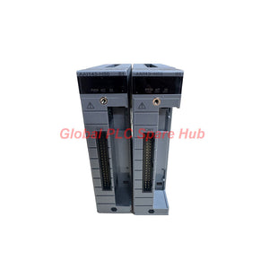
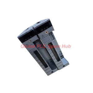
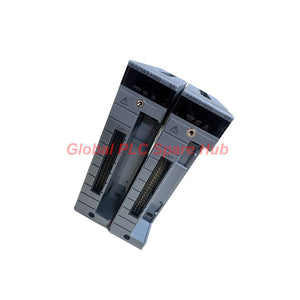
AAI143-H50/K4A00 Yokogawa CENTUM VP 16-Channel HART Analog Input Module
Manufacturer: Yokogawa
Product No.: AAI143-H50/K4A00
Condition: In stock
Product Type: Analog Input Module
Product Origin: SG
Payment: T/T, Western Union
Weight: 350g
Shipping port: Xiamen
Warranty: 12 months
Estimate delivery times: 12-26 days (International), 3-6 days (United States).
Return within 30 days of purchase. Duties & taxes are non-refundable.
Guaranteed Safe Checkout
Yokogawa AAI143-H50/K4A00 | 16-Channel Isolated HART Analog Input Module
The Yokogawa AAI143-H50/K4A00 is a 16-channel analog input module designed to acquire 4–20 mA signals from industrial field transmitters. It supports HART digital communication and provides isolated input channels for compatible control system configurations.
This configuration combines the AAI143 analog input function with a KS Cable Interface Adapter. The adapter connects to the AEA4D Terminal Board and carries the model designation ATK4A-00. Engineers should verify the terminal board, cable arrangement, and host-system compatibility before installation.
Application focus: Process signal acquisition, transmitter integration, and HART-enabled instrument maintenance in compatible Yokogawa control systems.
01 | Product Identity and Configuration Breakdown
| Manufacturer | Yokogawa |
| Full Model | AAI143-H50/K4A00 |
| Product Series | AAI143 |
| Product Type | Analog Input Module |
| Input Configuration | 16 isolated channels, 4–20 mA |
| Digital Communication | HART supported |
| Interface Adapter | KS Cable Interface Adapter, ATK4A-00 |
| Terminal Board Compatibility | AEA4D Terminal Board, subject to system verification |
Model code interpretation
- AAI143: Identifies the analog input module model.
- H: Digital communication with the HART protocol.
- 5: Standard configuration without explosion protection.
- 0: Basic type.
- K4A00: KS Cable Interface Adapter configuration for connecting the AEA4D Terminal Board. The specified adapter model is ATK4A-00.
Confirm the complete ordering code when selecting a replacement. Do not substitute a similar AAI143 variant without checking its communication features, protection type, and terminal interface.
02 | Electrical Performance and Input Characteristics
| Number of Input Channels | 16, isolated |
| Input Signal | 4–20 mA |
| Allowable Input Current | 24 mA |
| Input Accuracy | ±16 µA |
| Data Update Period | 10 ms |
| Input Resistance, Power ON | 270 Ω at 20 mA to 350 Ω at 4 mA |
| Input Resistance, Power OFF | 500 kΩ or greater |
| Input-to-System Withstand Voltage | 1500 V AC for 1 minute |
| Ambient Temperature Drift | ±16 µA per 10°C |
| Transmitter Supply | 19.0 V or higher at 20 mA; 25.5 V or lower at 0 mA |
| Transmitter Supply Current Limit | 25 mA |
| Maximum Current Consumption | 230 mA at 5 V DC; 540 mA at 24 V DC |
| Weight | 0.3 kg |
Engineering note: The 10 ms update period describes the specified data refresh interval. It does not establish the complete HART communication cycle time or the response time of the entire control loop.
03 | HART Communication and Transmitter Integration
The HART-enabled AAI143-H50/K4A00 supports analog current acquisition and HART digital communication. This combination helps engineers integrate process measurements with supported smart field instruments.
- Analog process values: Acquire 4–20 mA signals from compatible transmitters.
- Digital instrument access: Support HART communication when the host system, instrument, and configuration permit it.
- Transmitter wiring: Configure each channel for a 2-wire or 4-wire transmitter using the specified setting pin.
- Maintenance support: Use available HART data for instrument checks when the control system provides the required functions.
HART support does not guarantee that every instrument parameter will be accessible through every host system. Verify the instrument's HART revision, host capabilities, and engineering software configuration before commissioning.
04 | Cable Interface and Terminal Board Configuration
- Adapter: KS Cable Interface Adapter, model ATK4A-00.
- Terminal board: AEA4D Terminal Board.
- External connection options: Pressure clamp terminal, MIL connector cable, or dedicated KS1 cable, as applicable to the installed configuration.
- Replacement check: Verify the actual cable type, connector arrangement, terminal board model, and wiring diagram.
Do not assume that a physically similar cable or terminal board provides electrical compatibility. Check the approved system drawings before reconnecting field wiring.
05 | Compatible Equipment and Industrial Applications
This module suits compatible Yokogawa control system installations that require isolated 4–20 mA input acquisition and HART communication. Verify the exact host system and hardware revision before ordering.
- Pressure measurement: Acquire signals from compatible pressure transmitters in process pipelines and vessels.
- Temperature monitoring: Read 4–20 mA outputs from temperature transmitters.
- Flow measurement: Integrate compatible flow transmitters into process monitoring systems.
- Level measurement: Acquire level transmitter signals from storage tanks and process vessels.
- Chemical processing: Support distributed process measurement where the installed control system permits this module.
- Oil and gas: Support instrument signal acquisition in suitable process monitoring applications.
- Water treatment: Integrate compatible field transmitters into plant monitoring and control architectures.
The module is not a universal input card. Confirm the system series, I/O configuration, terminal board, and applicable project requirements before installation.
06 | Installation and Commissioning Procedure
- Verify the part number: Check AAI143-H50/K4A00 against the approved equipment list.
- Check the host system: Confirm the supported I/O configuration and hardware revision.
- Inspect the interface: Verify the ATK4A-00 adapter, AEA4D terminal board, and applicable cable arrangement.
- Isolate power: Follow site procedures before installing or disconnecting the module.
- Check field wiring: Confirm polarity, grounding, shielding, and terminal assignments.
- Set transmitter type: Configure each channel for the specified 2-wire or 4-wire arrangement.
- Verify the signal range: Confirm the configured input range and transmitter output.
- Check HART access: Verify communication through the supported host system and engineering tools.
- Perform a loop test: Compare known input current values with the displayed process values.
- Record results: Document channel assignments, test values, alarms, and configuration changes.
Follow the applicable Yokogawa installation manual for module insertion, removal, and energization. Do not assume that hot-swapping is supported.
07 | Diagnostics and Field Troubleshooting
Use a channel-by-channel approach to distinguish instrument faults from wiring, configuration, and module-related problems.
- Incorrect process value: Measure the loop current with an appropriate instrument. Compare the reading with the configured range and engineering units.
- Multiple channels show errors: Inspect shared wiring, common power sources, terminal interfaces, and system configuration before replacing the module.
- HART communication fails: Confirm instrument support, loop wiring, host configuration, and HART communication settings.
- Signal instability: Check shielding, grounding, electrical noise sources, and loose terminals.
- Temperature-related deviation: Review ambient conditions and compare observed errors with the specified temperature drift.
- Unexpected channel behavior: Confirm the 2-wire or 4-wire setting pin and verify the field instrument's wiring diagram.
Field example: A pressure reading remains incorrect after a transmitter replacement. Measure the loop current before changing the input module. If the current is correct but the displayed value is wrong, inspect channel scaling and engineering-unit settings first.
This example describes a general commissioning method. It does not represent a confirmed model-specific failure pattern.
08 | Environmental and Certification Verification
- Explosion protection: The specified suffix identifies a version without explosion protection.
- Input isolation: The supplied specification lists 1500 V AC withstand voltage between input and system for one minute.
- Temperature and humidity limits: Confirm the applicable installation limits in the official hardware documentation.
- Project compliance: Check area classification, cabinet requirements, and instrument-loop documentation before installation.
No additional certification details were supplied for this exact configuration. Request official documentation if the project requires specific approvals or formal compliance evidence.
09 | Packaging, Warranty, and Delivery
- Product: Yokogawa AAI143-H50/K4A00 Analog Input Module.
- Interface configuration: KS Cable Interface Adapter for the AEA4D Terminal Board, model ATK4A-00.
- Packaging: Protective packaging suitable for transport.
- Accessories: Confirm whether cables, terminal boards, and additional accessories are included in the quotation.
- Warranty: 12-month warranty, subject to the supplier's applicable terms and conditions.
- Shipping methods: FedEx, UPS, and DHL.
- Dispatch estimate: Typically 24–48 hours after order confirmation, subject to stock and payment verification.
Contact the sales team to confirm availability, included items, warranty coverage, and the estimated delivery schedule before ordering.
10 | Global PLC Spare HUB's Insight
When replacing an analog input module, engineers should verify more than the channel count and current range. The terminal interface and transmitter wiring configuration can determine whether an otherwise similar module fits the installed system.
For this configuration, the K4A00 suffix identifies the KS Cable Interface Adapter arrangement for the AEA4D Terminal Board. Check the adapter model, cable type, and approved wiring drawings before disconnecting the existing installation.
The 16 isolated channels and HART support also help define the module's role in instrument integration. However, HART access depends on the host system and instrument configuration. Confirm the required digital functions during engineering review rather than assuming full device-management support.
For a replacement quotation, provide the complete model, installed terminal board, required quantity, and host-system information. These details reduce configuration uncertainty and help avoid delays during commissioning.
11 | Frequently Asked Questions
1. How can engineers confirm the module's measurement accuracy during commissioning?
Apply known current values with a suitable loop calibrator. Compare the displayed values against the configured scaling and specified accuracy of ±16 µA. Record results across representative channels and investigate deviations before returning the loop to service.
2. What should be checked when only one input channel reports an incorrect value?
Inspect that channel's transmitter, wiring, setting pin, and scaling configuration first. Compare its behavior with a known-good channel when site procedures permit. Avoid replacing the entire module until field-side causes have been checked.
3. Can a 4–20 mA transmitter use HART communication on this module?
The module supports HART communication. Successful digital access also depends on the transmitter, host system, wiring, and engineering software. Verify these elements before planning device configuration or diagnostics through HART.
4. What details matter most when selecting a replacement for an installed AAI143 module?
Match the complete model code, explosion-protection option, communication capability, terminal board, and cable interface. Also confirm the installed control system's hardware compatibility and the required transmitter wiring arrangement.
5. How should engineers investigate temperature-related signal deviations?
Check cabinet temperature, loop current, wiring integrity, and transmitter stability. The supplied specification lists a drift of ±16 µA per 10°C. Confirm the applicable measurement conditions and manufacturer guidance before attributing the deviation to the module.
Request a Quotation
Looking for the Yokogawa AAI143-H50/K4A00 isolated analog input module? Contact Global PLC Spare HUB for pricing, availability, and shipping options.
Please provide the required quantity, host-system model, and terminal board configuration. Our team can review the part identification and quotation requirements before order confirmation.

Tags
Q: Are these parts 100% original and new?
A: Yes. Every component is guaranteed to be 100% original, brand-new, and factory-sealed. We also provide a 12-month comprehensive warranty for your peace of mind.
Q: How fast is the shipping to my country?
A: For in-stock items, we offer same-day dispatch. International express shipping (DHL/FedEx/UPS) typically delivers within 3–5 business days worldwide.
Q: Can I get a formal quotation with shipping costs?
A: Absolutely. Our sales team is ready to provide a detailed Proforma Invoice (PI) including the most competitive shipping rates for your location.
Q: Do you offer discounts for bulk orders?
A: We provide volume-based pricing for large projects or multiple-item orders. Please contact us to get our Best Price Guarantee.
12-Month Comprehensive Warranty
Every part supplied by Global PLC Spare Hub is covered by a 12-month warranty from the date of invoice.
- Coverage: Functional defects and hardware failures under normal operating conditions.
- Commitment: We provide immediate repair, replacement, or a full refund for any verified defective components to minimize your operational downtime.
Returns & Exchange Policy
We offer a 30-day return policy to ensure you receive the exact part your system requires.
- Eligibility: Returns are accepted for uninstalled items in their original, factory-sealed packaging.
- RMA Process: Please contact our support team to obtain a Return Merchandise Authorization (RMA) number before shipping.
- Fast Processing: Refunds or exchanges are processed within 3–5 business days after the returned item passes our technical inspection.
Need Technical Assistance?Not sure if this part is compatible with your system? [Consult our Engineers] before purchasing to ensure 100% compatibility.
People Also Bought


