


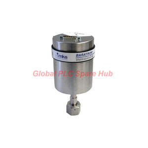
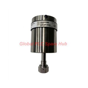
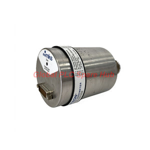
627H21TBC1B MKS Instruments 627H Heated Baratron Pressure Transducer
Manufacturer: MKS Instruments
Product No.: 627H21TBC1B
Condition: In stock
Product Type: Pressure Transducer Module
Product Origin: USA
Payment: T/T, Western Union
Weight: 500g
Shipping port: Xiamen
Warranty: 12 months
Estimate delivery times: 12-26 days (International), 3-6 days (United States).
Return within 30 days of purchase. Duties & taxes are non-refundable.
Guaranteed Safe Checkout
627H21TBC1B | Heated Absolute Pressure Measurement
MKS Instruments 627H21TBC1B is a heated absolute pressure transducer from the 627H (600 Series).
This model measures absolute pressure across a 20 Torr full-scale range. Its sensor operates at a controlled temperature of 45°C.
The heated design helps maintain stable sensor temperature during pressure measurement. Vertical calibration supports installations that require a defined calibration orientation.
The instrument provides a 0 to +10 VDC analog output. It operates from a ±15 VDC power supply and uses an Inconel wetted construction.
Model Identification
- Manufacturer: MKS Instruments
- Model: 627H21TBC1B
- Product Family: 627H (600 Series)
- Instrument Type: Heated Baratron Absolute Pressure Transducer
- Measurement Range: 0–20 Torr absolute
- Sensor Temperature: 45°C controlled
- Calibration Orientation: Vertical
- Output Signal: 0 to +10 VDC
- Process Connection: 8 VCR Female
01 | Measurement Architecture and Performance
The 627H21TBC1B uses a heated Baratron measurement platform. It measures absolute pressure rather than gauge or differential pressure.
| Measurement Parameter | Specification |
| Measurement Type | Absolute Pressure |
| Full-Scale Range | 20 Torr |
| Accuracy | 0.12% of Reading |
| Resolution | 0.001% of Full Scale |
| Non-Linearity | Included in specified accuracy |
| Hysteresis | Included in specified accuracy |
| Non-Repeatability | Included in specified accuracy |
| Warm-Up Time | 2 Hours |
| Calibration Position | Vertical |
Measurement Accuracy: The specified accuracy is 0.12% of reading. This specification includes non-linearity, hysteresis, and non-repeatability.
Measurement Resolution: The stated resolution equals 0.001% of full scale. At 20 Torr, this corresponds to 0.0002 Torr.
Resolution describes the smallest specified measurement increment. It does not represent absolute measurement accuracy.
02 | Thermal Control and Measurement Stability
The sensor maintains a controlled temperature of 45°C. This heated configuration helps reduce measurement variations associated with sensor temperature changes.
| Thermal Parameter | Specification |
| Controlled Sensor Temperature | 45°C |
| Operating Temperature | 15 to 40°C |
| Warm-Up Time | 2 Hours |
| Zero Temperature Coefficient | 0.002% FS/°C |
| Span Temperature Coefficient | 0.02% of Reading/°C |
Engineering Considerations:
- Allow the full two-hour warm-up period before critical measurements.
- Maintain ambient temperature within the specified operating range.
- Avoid rapid temperature changes around the instrument.
- Check zero stability after thermal stabilization.
- Evaluate span deviation when ambient conditions change.
The sensor temperature and ambient operating temperature describe different conditions. The 45°C internal setting does not change the specified 15–40°C ambient limit.
03 | Electrical Interface and Signal Integration
The transducer provides an analog voltage signal for pressure monitoring systems. Its electrical interface supports integration with compatible industrial measurement equipment.
| Electrical Parameter | Specification |
| Power Supply | ±15 VDC |
| Power Tolerance | ±5% |
| Maximum Current | 0.25 A |
| Analog Output | 0 to +10 VDC |
| Minimum Load Impedance | >10 kΩ |
| Electrical Connector | 15-Pin D-Sub |
| Connector Retention | Thread Locks |
| Trip Points | Not Available |
| Heater Status LED | Not Available |
Analog Signal Interpretation
Assuming a linear 0–10 V output across the 0–20 Torr range:
- 0 V corresponds to 0 Torr.
- 2.5 V corresponds to 5 Torr.
- 5 V corresponds to 10 Torr.
- 7.5 V corresponds to 15 Torr.
- 10 V corresponds to 20 Torr.
Use the actual instrument transfer function when configuring the receiving system. Verify the output scaling before commissioning.
PLC and Data Acquisition Integration:
- Use a compatible voltage input channel.
- Confirm the input impedance exceeds 10 kΩ.
- Provide the required bipolar ±15 VDC supply.
- Verify signal common and grounding arrangements.
- Use shielded wiring where the installation requires it.
- Check electrical noise before adjusting measurement scaling.
04 | Process Connection and Wetted Construction
The pressure boundary uses Inconel wetted materials. The process connection features an 8 VCR female fitting.
| Mechanical Parameter | Specification |
| Wetted Material | Inconel |
| Process Fitting | 8 VCR Female |
| Internal Volume | 6.3 cc |
| Overpressure Limit | 45 psia (310 kPa) or 120% FS, whichever is greater |
| Diameter | 3.15 in (80.0 mm) |
| Body Height | 3.87 in (98.4 mm) |
| Stem Length | 1.38 in (35.1 mm) |
Installation Space: Allow sufficient clearance for the sensor body, stem, process fitting, and electrical connector.
Pressure Protection: The overpressure limit does not represent a normal operating pressure range. Avoid pressure excursions beyond the specified limit.
05 | Installation and Commissioning Procedure
Mechanical Installation
- Confirm the mounting position matches the vertical calibration orientation.
- Check the 8 VCR female connection against the process line.
- Inspect sealing surfaces before connecting the pressure line.
- Use compatible VCR sealing components.
- Avoid excessive mechanical loading on the instrument body.
- Keep the installation within the specified pressure limits.
Electrical Installation
- Verify the bipolar ±15 VDC power supply.
- Check supply polarity and voltage tolerance.
- Inspect the 15-pin D-sub connector.
- Secure the connector using its thread locks.
- Connect the analog output to a suitable voltage input.
- Verify signal common and grounding arrangements.
Commissioning Sequence
- Apply the specified power supply.
- Allow at least two hours for warm-up.
- Confirm stable ambient temperature.
- Check the zero-pressure reference under suitable conditions.
- Apply known pressure points using a calibrated reference.
- Compare the output voltage with the expected pressure.
- Confirm the receiving controller displays the correct engineering units.
06 | Diagnostic Checks and Maintenance
Practical Troubleshooting Reference
| Observed Condition | Recommended Inspection |
| No Analog Output | Check ±15 VDC supply, connector wiring, and receiving input. |
| Output Does Not Reach Expected Value | Verify pressure reference and analog scaling. |
| Zero Reading Drifts | Check warm-up completion and ambient temperature stability. |
| Unstable Pressure Display | Inspect pressure connections, grounding, and signal wiring. |
| Slow Stabilization | Check thermal stabilization and process pressure conditions. |
| Unexpected Calibration Deviation | Verify mounting orientation and calibration reference. |
Maintenance Recommendations
- Inspect process fittings during scheduled maintenance.
- Check supply voltage before investigating measurement errors.
- Keep the electrical connector clean and secure.
- Record zero and span verification results.
- Use suitable reference equipment for calibration checks.
- Follow MKS service procedures for internal repairs.
This model has no trip points or heater status LED. Engineers should verify operating conditions through external measurements and system diagnostics.
07 | Application and System Integration
The 20 Torr absolute measurement range suits low-pressure monitoring applications. The analog output supports integration with compatible pressure monitoring systems.
- Semiconductor Equipment: Pressure monitoring in compatible process chambers and vacuum equipment.
- Vacuum Systems: Absolute pressure measurement within the configured range.
- Thin-Film Processes: Pressure feedback for suitable deposition equipment.
- Gas Delivery Systems: Pressure monitoring in compatible low-pressure gas lines.
- Industrial Instrumentation: Analog pressure measurement through PLC and data acquisition interfaces.
Application suitability depends on process gas compatibility, pressure conditions, installation design, and required measurement performance.
08 | Model Selection and Ordering Verification
Several configuration details determine whether this instrument matches an existing installation. Verify the complete model number before purchasing.
- Measurement Range: Confirm the required 20 Torr full scale.
- Measurement Type: Verify absolute pressure measurement.
- Heating Configuration: Confirm the 45°C sensor temperature.
- Calibration: Check the vertical calibration requirement.
- Output: Confirm the 0–10 VDC signal interface.
- Power: Verify the ±15 VDC supply availability.
- Connection: Confirm the 8 VCR female fitting.
- Material: Check Inconel compatibility with the process.
Ordering Tip: A matching 20 Torr range alone does not guarantee interchangeability. Compare the electrical interface, calibration orientation, heating configuration, and process connection.
09 | Compliance and Package Information
Compliance
- CE compliant.
Confirm the applicable declaration and documentation for the exact supplied configuration.
Package Contents
- 1 × MKS Instruments 627H21TBC1B Heated Baratron Pressure Transducer.
- Additional accessories and documentation depend on the confirmed order configuration.
Power cables, mating connectors, calibration certificates, and mounting accessories require separate confirmation.
10 | Technical FAQ
Q1: Why does the installation require vertical calibration orientation?
Calibration orientation defines the reference position for specified measurement performance. Mechanical orientation can affect pressure sensor readings in certain designs.
Install the instrument in its specified vertical position. If the equipment requires another orientation, consult MKS before installation.
Q2: How should engineers distinguish sensor resolution from system accuracy?
Resolution describes the smallest specified measurement increment. Accuracy describes how closely the measured value represents the actual pressure.
For this model, resolution is 0.0002 Torr. Its specified accuracy is 0.12% of reading.
PLC input resolution and signal noise can reduce the effective measurement resolution of the complete system.
Q3: What can cause an incorrect pressure reading after replacing the transducer?
Common causes include incorrect signal scaling, unsuitable mounting orientation, and incompatible power supplies.
Engineers should also check the 8 VCR connection and the receiving instrument configuration.
Compare the analog output against a calibrated pressure reference before changing controller parameters.
Q4: Why should engineers wait two hours before performing calibration checks?
The internal sensor uses controlled heating at 45°C. Its thermal condition needs time to stabilize after power-up.
Performing calibration checks too early can introduce misleading zero or span deviations.
Allow the specified warm-up period before evaluating measurement performance.
Q5: What should buyers verify when selecting this model for vacuum equipment?
First, confirm that 20 Torr absolute pressure covers the actual process operating range.
Next, verify the vertical calibration, 45°C heating configuration, and 0–10 VDC output.
Check the available ±15 VDC supply and 8 VCR female connection. Also confirm Inconel compatibility with the process media.
For replacement projects, provide the original nameplate photograph and equipment interface details before ordering.

Tags
Q: Are these parts 100% original and new?
A: Yes. Every component is guaranteed to be 100% original, brand-new, and factory-sealed. We also provide a 12-month comprehensive warranty for your peace of mind.
Q: How fast is the shipping to my country?
A: For in-stock items, we offer same-day dispatch. International express shipping (DHL/FedEx/UPS) typically delivers within 3–5 business days worldwide.
Q: Can I get a formal quotation with shipping costs?
A: Absolutely. Our sales team is ready to provide a detailed Proforma Invoice (PI) including the most competitive shipping rates for your location.
Q: Do you offer discounts for bulk orders?
A: We provide volume-based pricing for large projects or multiple-item orders. Please contact us to get our Best Price Guarantee.
12-Month Comprehensive Warranty
Every part supplied by Global PLC Spare Hub is covered by a 12-month warranty from the date of invoice.
- Coverage: Functional defects and hardware failures under normal operating conditions.
- Commitment: We provide immediate repair, replacement, or a full refund for any verified defective components to minimize your operational downtime.
Returns & Exchange Policy
We offer a 30-day return policy to ensure you receive the exact part your system requires.
- Eligibility: Returns are accepted for uninstalled items in their original, factory-sealed packaging.
- RMA Process: Please contact our support team to obtain a Return Merchandise Authorization (RMA) number before shipping.
- Fast Processing: Refunds or exchanges are processed within 3–5 business days after the returned item passes our technical inspection.
Need Technical Assistance?Not sure if this part is compatible with your system? [Consult our Engineers] before purchasing to ensure 100% compatibility.
People Also Bought


