


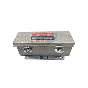
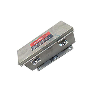
24765-01-00 Bently Nevada 24765 Series DC Case Expansion Sensor Assembly
Manufacturer: Bently Nevada
Product No.: 24765-01-00
Condition: In stock
Product Type: Case Expansion Transducer Assembly
Product Origin: USA
Payment: T/T, Western Union
Weight: 500g
Shipping port: Xiamen
Warranty: 12 months
Estimate delivery times: 12-26 days (International), 3-6 days (United States).
Return within 30 days of purchase. Duties & taxes are non-refundable.
Guaranteed Safe Checkout
Bently Nevada 24765-01-00 DC Case Expansion Transducer Assembly
The Bently Nevada 24765-01-00 is a DC case expansion transducer assembly designed to measure relative displacement associated with machinery casing movement. It uses an LVDT-based sensing arrangement to convert mechanical plunger movement into a proportional DC voltage signal for monitoring and protection applications.
In turbine and other large rotating machinery installations, casing expansion measurements help engineers evaluate thermal growth during startup, shutdown, and changing operating loads. The transducer provides a defined linear measurement range and electrical scale factor, allowing the monitoring system to interpret casing movement as an engineering value.
The specified 24765-01 configuration has a scale factor of 0.346 V/mm (8.79 V/in), a linear range of ±12.7 mm (±0.5 in), and a -3 dB frequency of 20 Hz.
Ordering Code Structure
The complete part number identifies the case expansion transducer assembly and its selected linear-range and spring-return options.
| Code | Configuration | Engineering Description |
|---|---|---|
| 24765 | Product family | Bently Nevada DC case expansion transducer assembly |
| 01 | Linear range option | 25.4 mm (1.0 in) nominal full linear range option |
| 00 | Spring option | Without spring return |
Configuration interpretation: The -01 option corresponds to the 25.4 mm (1.0 in) total linear range, expressed in the supplied performance data as ±12.7 mm (±0.5 in). The -00 suffix specifies a configuration without spring return. Confirm the required plunger arrangement and mechanical travel before replacing an installed assembly.
Displacement Measurement and Electrical Performance
| Parameter | 24765-01 Specification |
|---|---|
| Measurement principle | DC LVDT assembly |
| Scale factor | 0.346 V/mm (8.79 V/in) |
| Linear range | ±12.7 mm (±0.5 in) |
| -3 dB frequency | 20 Hz |
| Input power | +24 VDC, 30 mA minimum |
| Output ripple | Less than 1% of full scale |
| Linearity | ±0.5% of full range |
| Stability | 0.125% of full scale |
| Scale factor temperature coefficient | 0.07%/°C (0.04%/°F) |
The scale factor defines the relationship between plunger displacement and output voltage. When configuring the monitoring channel, engineers should use the scale factor specified for the installed transducer rather than applying a generic LVDT conversion value.
The 20 Hz -3 dB frequency indicates the dynamic response limit stated for this configuration. Case expansion is generally a relatively slow mechanical measurement, but the monitoring channel must still be configured to capture the expected movement without introducing unsuitable filtering or scaling.
Mechanical Construction and Installation Interfaces
The assembly uses a magnetic stainless steel body and a laminated glass-epoxy coil construction. Its mechanical design includes a threaded core end and machine-threaded mounting end. The plunger length is selected according to the installation geometry.
| Mechanical Parameter | Specification |
|---|---|
| Body material | Series 400 magnetic stainless steel |
| Coil construction | Laminated glass epoxy |
| Lead wire | 25 AWG stranded copper, Teflon-insulated |
| Lead wire length | 31 cm (12 in) |
| Core-end thread | 6-40 UNF-2B |
| Machine-end thread | 1/4-20 UNC-2A |
| Plunger length | Application-dependent |
| Height | 88.9 mm (3.50 in) |
| Width | 117 mm (4.60 in) |
| Length | 241 mm (9.50 in), for 24765-01 and -02 as specified |
| Weight | 2.3 kg (5.0 lb) |
Plunger length is an application-specific mechanical parameter. Before installation, compare the available travel, mounting position, casing movement direction, and linkage geometry with the equipment drawing. Incorrect plunger length or alignment can cause the assembly to operate outside its intended linear region.
Operating Environment and Mechanical Durability
| Environmental Parameter | Specification |
|---|---|
| Operating temperature | -18°C to +71°C (0°F to +160°F) |
| Storage temperature | -54°C to +93°C (-65°F to +200°F) |
| Shock resistance | 250 g for 11 ms |
| Vibration resistance | 10 g at 0–2 kHz |
| Manufacturing origin | Made in U.S.A., as specified |
The supplied documentation also lists a separate environmental-limits set: operating temperature of -25°C to +85°C and storage temperature of -55°C to +125°C, with the same stated shock and vibration limits. These values should not be combined automatically with the model-specific operating and storage temperatures above. Confirm which limits apply to the exact assembly revision and installation conditions before final engineering approval.
Application in Turbine Casing Expansion Monitoring
During turbine operation, thermal gradients cause the casing and supporting structures to expand or contract. The resulting displacement must be measured in relation to the installed reference point. A case expansion transducer provides the displacement signal used by the monitoring system to track this movement.
- Steam turbines: Monitor casing movement during warm-up, load changes, and cooldown.
- Gas turbines: Support casing displacement monitoring as thermal conditions change.
- Power generation equipment: Provide measurement input for machinery condition monitoring and operational assessment.
- Large rotating machinery: Track structural movement where casing expansion is an important operating parameter.
Commissioning and Troubleshooting Guidance
- Inspect the mechanical installation: Check the mounting threads, plunger length, alignment, and available travel. Ensure the plunger does not bind during the expected casing movement.
- Verify the power supply: Confirm the +24 VDC supply and its ability to provide at least 30 mA.
- Check the monitoring channel: Confirm the configured scale factor and measurement range match the installed -01 assembly.
- Review the output signal: Compare voltage changes with known or expected mechanical displacement. Check for unstable readings, clipping, or unexpected offset changes.
- Validate movement across the operating range: Where the commissioning procedure permits, verify that the transducer operates within its specified linear range throughout the expected casing travel.
If the indicated displacement does not agree with the mechanical reference, check the scaling configuration before assuming that the transducer has failed. Also inspect the plunger linkage for friction, misalignment, or restricted movement. These mechanical issues can create measurement errors even when the electrical supply is correct.
Selection Notes for Replacement Projects
For replacement selection, the complete model number is only the starting point. Engineers should compare the linear range, scale factor, spring-return option, plunger length, mounting threads, and monitoring-system input requirements.
In particular, do not substitute a different 24765 range option solely because the physical assembly appears similar. A different range may have a different electrical scale factor and output relationship. The monitoring channel must use the correct conversion data for the installed transducer.
Warranty and Shipping
- Warranty period: 12 months.
- Shipping methods: FedEx, UPS, and DHL.
- Ordering support: Provide the complete part number and application details for configuration verification.
Frequently Asked Questions
1. What is the difference between case expansion and shaft displacement measurement?
Case expansion measurement tracks movement of the machine casing or its supporting structure, often caused by thermal growth. Shaft displacement measurement focuses on the position of the rotating shaft relative to a reference point. These measurements serve different diagnostic purposes and require sensors with different mechanical arrangements and installation locations.
2. Why should the plunger length be confirmed before ordering?
The plunger must match the distance between the transducer mounting position and the machine's measurement interface. If it is too short, the assembly may not maintain the required mechanical engagement. If it is too long, the plunger may have insufficient travel clearance or may operate outside its intended range. Use the equipment drawing and existing installation dimensions to confirm the required length.
3. What could cause a displacement reading to drift as the turbine temperature changes?
Possible causes include the specified scale-factor temperature coefficient, changes in the mounting structure, mechanical friction, and signal-conditioning errors. Compare the reading with the expected thermal movement and review the monitoring channel's scaling. Also check whether the sensor is operating within its specified temperature limits.
4. Can a 24765 assembly with spring return replace the -00 version?
Not without checking the mechanical design. The -00 configuration is specified as without spring return. A spring-return version introduces a different mechanical force condition at the plunger and may affect the interaction with the machine linkage. Confirm the required return mechanism and the equipment manufacturer's installation requirements before selecting another suffix.
5. How should engineers interpret conflicting scale-factor or frequency specifications in different documents?
Use the data tied to the exact model suffix and approved assembly drawing. The supplied information includes both a 24765-01 specification of 0.346 V/mm and 20 Hz, and a separate general 24765 DC LVDT description listing 0.404 V/mm and 15 Hz. These values should not be mixed. Verify the exact configuration and document revision before setting the monitoring channel or approving a replacement.
Technical Summary
The Bently Nevada 24765-01-00 is a DC case expansion transducer assembly for monitoring casing displacement in turbine and other large machinery applications. Its specified -01 configuration provides a ±12.7 mm linear range, a 0.346 V/mm scale factor, and a 20 Hz -3 dB frequency response. The -00 suffix identifies the version without spring return. Correct selection depends on matching the mechanical travel, plunger dimensions, electrical scaling, and monitoring-system configuration to the installed application.
Tags
Q: Are these parts 100% original and new?
A: Yes. Every component is guaranteed to be 100% original, brand-new, and factory-sealed. We also provide a 12-month comprehensive warranty for your peace of mind.
Q: How fast is the shipping to my country?
A: For in-stock items, we offer same-day dispatch. International express shipping (DHL/FedEx/UPS) typically delivers within 3–5 business days worldwide.
Q: Can I get a formal quotation with shipping costs?
A: Absolutely. Our sales team is ready to provide a detailed Proforma Invoice (PI) including the most competitive shipping rates for your location.
Q: Do you offer discounts for bulk orders?
A: We provide volume-based pricing for large projects or multiple-item orders. Please contact us to get our Best Price Guarantee.
12-Month Comprehensive Warranty
Every part supplied by Global PLC Spare Hub is covered by a 12-month warranty from the date of invoice.
- Coverage: Functional defects and hardware failures under normal operating conditions.
- Commitment: We provide immediate repair, replacement, or a full refund for any verified defective components to minimize your operational downtime.
Returns & Exchange Policy
We offer a 30-day return policy to ensure you receive the exact part your system requires.
- Eligibility: Returns are accepted for uninstalled items in their original, factory-sealed packaging.
- RMA Process: Please contact our support team to obtain a Return Merchandise Authorization (RMA) number before shipping.
- Fast Processing: Refunds or exchanges are processed within 3–5 business days after the returned item passes our technical inspection.
Need Technical Assistance?Not sure if this part is compatible with your system? [Consult our Engineers] before purchasing to ensure 100% compatibility.
People Also Bought


