


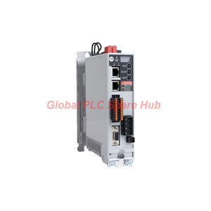
2198-C4020-ERS Allen-Bradley Kinetix 5300 Servo Drive | 3.9 kW Motion Control
Manufacturer: Allen-Bradley
Product No.: 2198-C4020-ERS
Condition: In stock
Product Type: Servo Drive
Product Origin: USA
Payment: T/T, Western Union
Weight: 2270g
Shipping port: Xiamen
Warranty: 12 months
Estimate delivery times: 12-26 days (International), 3-6 days (United States).
Return within 30 days of purchase. Duties & taxes are non-refundable.
Guaranteed Safe Checkout
Allen-Bradley 2198-C4020-ERS — Kinetix 5300 Single-Axis Servo Drive
The 2198-C4020-ERS is a single-axis servo drive in the Allen-Bradley Kinetix 5300 family. It provides coordinated motor control through an EtherNet/IP interface and supports linear or ring network topologies. The supplied specifications identify a 380–480 V AC, three-phase input and 3.9 kW continuous output rating.
For machine builders and maintenance engineers, the drive’s key selection points are its voltage class, continuous and peak current, motor feedback requirements, network layout, digital I/O and Safe Torque Off (STO) interface. Confirm that the selected motor, feedback device and safety architecture match the installed system before commissioning.
Drive Profile — Ratings at a Glance
| Manufacturer | Allen-Bradley (Rockwell Automation) |
| Part number | 2198-C4020-ERS |
| Product family | Kinetix 5300 |
| Drive type | Single-axis servo drive |
| Input supply | 380–480 V AC, three-phase |
| Input frequency | 50–60 Hz |
| Continuous output power | 3.9 kW |
| Continuous current | 7.3 A RMS |
| Peak current | 10.3 A peak |
| Network | Two RJ45 EtherNet/IP ports; linear or ring topology |
| Encoder power | 5 V DC and 9 V DC supply options |
| Digital inputs | Four 24 V DC sinking inputs |
| Safety interface | Dual-channel Safe Torque Off (STO) input |
| Brake control | 24 V DC brake output |
| Short-circuit rating | 200 kA, as supplied in the product data; verify the required upstream protection and installation conditions in the manufacturer’s documentation |
| Weight | 5.00 lb (2.27 kg) |
| UPC | 191326677646 |
Control Architecture — How the Drive Fits into a Machine
- Motion command: The controller communicates with the drive over EtherNet/IP. The two RJ45 ports support the stated linear or ring network arrangements.
- Motor feedback: The drive provides 5 V DC and 9 V DC encoder power options. Confirm the specific motor and feedback-device compatibility, connector pinout and feedback type using the drive and motor manuals.
- Machine I/O: Four 24 V DC sinking inputs support compatible control signals. Check input logic and wiring requirements before connecting sensors or machine signals.
- Brake interface: The 24 V DC brake output can be used with a compatible motor brake circuit. Verify the brake’s electrical rating and required external components.
- Safety circuit: The dual-channel STO input is intended for integration into an appropriate safety control system. STO removes torque-producing capability; it does not itself provide electrical isolation or mechanically stop a moving load.
Where It Can Be Used
- Packaging and converting machinery: Axis control for indexing, feeding, sealing, cutting and coordinated machine movement, where the motor and load fall within the drive’s ratings.
- Material handling: Servo-driven positioning and transfer mechanisms in compatible conveyor, pick-and-place or handling equipment.
- Assembly and automation stations: Single-axis motion in fixtures, actuators and automated production equipment.
- Machine tools and process equipment: Motion applications requiring controlled positioning or speed, subject to motor, load and duty-cycle sizing.
- EtherNet/IP machine networks: Systems using a compatible controller and a supported network topology.
These are application categories, not confirmation of a specific machine’s compatibility. Final selection depends on motor voltage and current, torque and speed requirements, inertia, duty cycle, feedback device, regenerative-energy handling, controller support and the machine’s safety design.
Engineering Checks Before Installation
- Verify the supply: Confirm that the incoming three-phase supply is within the specified 380–480 V AC range and that the installation meets the manufacturer’s grounding and protection requirements.
- Size the motor and axis: Compare the motor’s continuous and peak current demands with the drive’s 7.3 A RMS continuous and 10.3 A peak ratings. Check acceleration, deceleration and thermal duty—not just nominal motor power.
- Confirm feedback: Match the motor feedback technology and required encoder supply to the drive’s supported configuration. Do not assume that every 5 V or 9 V encoder is compatible.
- Plan the network: Confirm controller compatibility, IP addressing, topology and the required EtherNet/IP configuration. Use the prescribed cabling and network practices.
- Validate safety: Design and validate the dual-channel STO circuit according to the machine risk assessment and applicable safety requirements. Do not treat STO as a lockout or energy-isolation device.
- Check brake behavior: Verify the motor brake’s voltage, current, timing and control sequence. A brake output alone does not establish that a load will be safely held under every fault condition.
Diagnostics and Troubleshooting Approach
Use the drive’s status and fault information available through the applicable Rockwell Automation tools and manuals. The specifications provided here do not identify individual fault codes, so the following are diagnostic checks rather than a fault-code list.
- Drive will not enable: Check supply conditions, controller-to-drive communication, configuration, active faults and the state of the STO channels.
- EtherNet/IP connection issue: Inspect network cabling, port connections, device addressing, controller configuration and network topology. Check whether the intended linear or ring architecture is supported and configured correctly.
- Motor feedback fault: Verify feedback-device compatibility, wiring, connector seating and encoder supply requirements. Inspect for cable damage or electrical noise.
- Axis trips during acceleration: Compare commanded motion and load demand with current and torque limits. Review acceleration, inertia mismatch, mechanical binding and the application duty cycle.
- Unexpected stopping or torque removal: Check the STO circuit and safety-controller status. Determine whether the stop resulted from a safety command, drive fault or control-system event.
- Brake-related movement: Verify brake wiring and sequencing, mechanical brake condition, and whether the brake is rated to hold the load. Follow the manufacturer’s procedure for safe testing.
Global PLC Spare HUB's Insight
For a replacement or expansion project, treat 2198-C4020-ERS as a complete drive configuration, not simply a 3.9 kW rating. The most important pre-order checks are the actual motor/feedback pairing, controller and EtherNet/IP setup, supply voltage, brake requirements and STO circuit design.
In practical commissioning, record the existing axis parameters and fault history before swapping hardware. After installation, verify network connection, motor feedback, direction of travel, brake operation and the safety response under an approved test procedure. Begin with a controlled, low-risk motion test before returning the machine to production.
Warranty and Shipping
- Warranty: 12-month warranty, subject to applicable supplier terms.
- Shipping options: FedEx, UPS and DHL, subject to destination and service availability.
- Dispatch: Timing is confirmed after stock and order verification.
- Compatibility support: Share the complete drive part number, motor model and controller/network details when requesting a quotation.
Frequently Asked Questions
1. How do I determine whether this drive has enough capacity for my servo motor?
Compare the motor’s rated and peak current with the drive ratings, then evaluate torque demand across the complete motion profile. Include acceleration, deceleration, load inertia, duty cycle and thermal limits. A motor’s kW value alone is not sufficient for sizing.
2. Can I replace another Kinetix drive with this model without changing the machine configuration?
Do not assume a drop-in replacement based only on the Kinetix family. Confirm the exact drive catalog number, motor and feedback compatibility, power wiring, controller support, network configuration, mounting and safety connections. Review the applicable migration or replacement documentation.
3. What should I check if the drive communicates over EtherNet/IP but the axis does not move?
Check the axis enable sequence, active drive faults, STO channel status, motor feedback, motion configuration and commanded limits. A healthy network connection does not prove that the axis is enabled or that its safety conditions are satisfied.
4. Is the dual-channel STO input sufficient to meet the machine’s safety requirements?
Not by itself. The required safety performance depends on the complete safety function, including the safety controller, wiring, risk assessment, validation and applicable standards. STO prevents torque production but does not provide electrical isolation or guarantee that a suspended or moving load is mechanically secured.
5. What details should I send when requesting a quotation for a spare drive?
Provide the full catalog number, motor nameplate data, feedback type, controller model, supply voltage, network arrangement and any brake or safety-interface requirements. If replacing an installed drive, include its application and fault symptoms to help assess whether the same configuration is appropriate.
Tags
Q: Are these parts 100% original and new?
A: Yes. Every component is guaranteed to be 100% original, brand-new, and factory-sealed. We also provide a 12-month comprehensive warranty for your peace of mind.
Q: How fast is the shipping to my country?
A: For in-stock items, we offer same-day dispatch. International express shipping (DHL/FedEx/UPS) typically delivers within 3–5 business days worldwide.
Q: Can I get a formal quotation with shipping costs?
A: Absolutely. Our sales team is ready to provide a detailed Proforma Invoice (PI) including the most competitive shipping rates for your location.
Q: Do you offer discounts for bulk orders?
A: We provide volume-based pricing for large projects or multiple-item orders. Please contact us to get our Best Price Guarantee.
12-Month Comprehensive Warranty
Every part supplied by Global PLC Spare Hub is covered by a 12-month warranty from the date of invoice.
- Coverage: Functional defects and hardware failures under normal operating conditions.
- Commitment: We provide immediate repair, replacement, or a full refund for any verified defective components to minimize your operational downtime.
Returns & Exchange Policy
We offer a 30-day return policy to ensure you receive the exact part your system requires.
- Eligibility: Returns are accepted for uninstalled items in their original, factory-sealed packaging.
- RMA Process: Please contact our support team to obtain a Return Merchandise Authorization (RMA) number before shipping.
- Fast Processing: Refunds or exchanges are processed within 3–5 business days after the returned item passes our technical inspection.
Need Technical Assistance?Not sure if this part is compatible with your system? [Consult our Engineers] before purchasing to ensure 100% compatibility.
People Also Bought


