


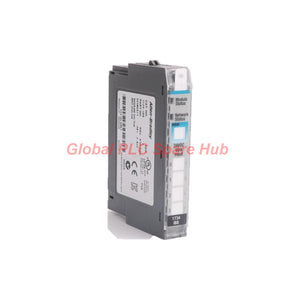
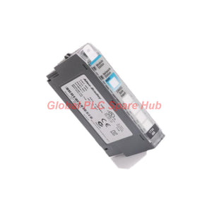
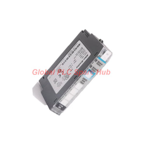
1734-IB8 Allen-Bradley POINT I/O 8-Channel 24V DC Input Module
Manufacturer: Allen-Bradley
Product No.: 1734-IB8
Condition: In stock
Product Type: DC Input Module
Product Origin: USA
Payment: T/T, Western Union
Weight: 540g
Shipping port: Xiamen
Warranty: 12 months
Estimate delivery times: 12-26 days (International), 3-6 days (United States).
Return within 30 days of purchase. Duties & taxes are non-refundable.
Guaranteed Safe Checkout
1734-IB8 | Allen-Bradley POINT I/O Digital Input Module
The Allen-Bradley 1734-IB8 is an eight-channel, 24V DC digital input module in the POINT I/O family from Rockwell Automation. It monitors discrete field signals and transfers input states to a compatible controller through a POINT I/O communication adapter.
Its sinking input configuration supports industrial DC signal circuits. Each channel includes a yellow status indicator for local troubleshooting. A configurable input filter helps engineers balance signal response against electrical noise and contact bounce.
The compact 12 mm-wide module installs on a compatible 1734-TB or 1734-TBS terminal base. It supports distributed I/O installations where machine sensors and control equipment connect through a modular POINT I/O system.
01 | Configuration Breakdown
| Configuration Item | Identification or Function |
| Catalog Number | 1734-IB8 |
| Brand | Allen-Bradley |
| Manufacturer | Rockwell Automation |
| Product Family | POINT I/O |
| Module Type | Digital DC sinking input module |
| Channel Configuration | 8 discrete input channels |
| Nominal Input Voltage | 24V DC |
| Terminal Base | 1734-TB or 1734-TBS |
| Required Keyswitch Position | Position 1 |
| Mounting Method | Compatible mounting base on DIN rail |
| Enclosure Type | Open-style |
Catalog number interpretation:
- 1734 — Identifies the POINT I/O product family.
- IB — Identifies a DC sinking input module.
- 8 — Indicates eight input channels.
This breakdown explains the catalog number's functional meaning. It does not define additional hardware revisions or option suffixes.
02 | Electrical and Input Performance
| Parameter | Specification |
| Input Voltage Range | 10–28.8V DC |
| Nominal Input Current | 4 mA per channel at 24V DC |
| Input Current Range | 2–5 mA |
| Maximum Input Current | 5 mA |
| Hardware Input Filter | 0.5 ms |
| Configurable Input Filter | 0–63 ms |
| POINTBus Current | 75 mA at 5V DC |
| Power Dissipation | 1.6 W |
| Thermal Dissipation | 5.5 BTU/hour |
| Isolation Voltage | 50V continuous, according to supplied specifications |
| Isolation Test | 2500V DC for 60 seconds, according to supplied specifications |
| Isolation Type | Reinforced insulation, field side to system side, as specified |
Input filter selection: A shorter filter setting improves response to fast input transitions. A longer setting can help reject brief disturbances and contact bounce. Validate the setting against the sensor response and machine cycle time.
03 | Mechanical Design and Environmental Conditions
| Dimension | Value |
| Height | 56 mm |
| Width | 12 mm |
| Depth | 75.5 mm |
| Approximate Weight | 31.8 g; some supplied descriptions state 32.3 g |
| Terminal Base Screw Torque | 0.8 N·m, as specified in the supplied information |
| Operating Temperature | -21°C to 55°C, as reported in the supplied information |
| Maximum Surrounding Air Temperature | 55°C |
| Mounting Orientation | Horizontal or vertical, subject to installation requirements |
| Enclosure Rating | Open-style |
| UPC | 10612598308573 |
Verification note: Confirm temperature limits, isolation ratings, mounting orientation, and terminal torque against the applicable Rockwell Automation installation manual. Use the approved installation conditions for the exact hardware revision.
04 | LED Status and Fault Isolation
| Indicator | Purpose | Engineering Check |
| Module Status | Green/red indicator for module status | Check module health and the controller's diagnostic information. |
| Input Status | Eight yellow indicators, one per channel | Compare each LED with the actual field input state. |
| Network Status | Listed in the supplied description | Verify adapter and network status through the complete POINT I/O system. |
The available descriptions differ in how they count status indicators. Confirm the exact indicator arrangement and meanings using the hardware label and official manual.
Practical diagnostic sequence:
- Check the field sensor's supply voltage and switching output.
- Measure the input signal at the terminal base using an appropriate meter.
- Compare the measured signal with the channel's yellow LED.
- Inspect the terminal seating, wiring polarity, and terminal-base connections.
- Review controller input data and adapter diagnostics.
- Check filter settings if brief signals fail to register or noisy signals trigger unwanted transitions.
Diagnostic limitation: The module's LEDs support local fault isolation. They do not independently identify every sensor, wiring, network, or controller fault.
05 | Integration with POINT I/O Systems
- Communication adapters: Designed for compatible POINT I/O communication adapters.
- Distributed architecture: Places discrete input monitoring near machine sensors and field devices.
- Terminal base requirement: Requires a compatible 1734-TB or 1734-TBS wiring base assembly.
- DeviceNet and PROFIBUS: The supplied product description reports compatibility for Series C modules with applicable adapters. Verify the exact revision and adapter combination before ordering.
- Controller integration: Confirm controller configuration, adapter support, module revision, and I/O mapping.
Do not select a communication adapter from protocol name alone. Check the controller architecture, network interface, firmware requirements, and installed POINT I/O revisions.
06 | Installation and Commissioning
- Confirm the part number: Match the module label to 1734-IB8 and verify the hardware revision.
- Prepare the mounting base: Install a compatible 1734-TB or 1734-TBS base on the approved DIN rail arrangement.
- Set the key switch: Use position 1 as specified for this module.
- Wire the field signals: Follow the official terminal diagram and verify the DC input circuit design.
- Check terminal torque: Apply the specified torque from the applicable installation manual.
- Configure the adapter: Add the module to the supported I/O configuration and verify the input mapping.
- Test every channel: Switch each sensor or test input and confirm the corresponding LED and controller data.
- Set the input filter: Adjust the configurable delay according to sensor behavior and required response time.
Disconnect power where required before installation or wiring. Follow the plant's electrical safety procedures and use suitable protection against accidental contact.
07 | Typical Equipment and Application Scenarios
- Packaging lines: Read photoelectric sensors, part-present switches, and conveyor position signals.
- Assembly machines: Monitor fixture confirmation, cylinder limit switches, and component detection signals.
- Material handling: Collect discrete states from conveyor sections, transfer stations, and access mechanisms.
- Water and process skids: Monitor compatible DC switches and discrete equipment status signals.
- Machine tools: Collect auxiliary position switches and machine-state inputs within the approved control design.
- Distributed control panels: Expand local discrete input capacity through a compatible POINT I/O adapter.
Use the 1734-IB8 for compatible DC discrete signals. It is not an analog input module and does not directly measure temperature, pressure, flow, or other analog process variables.
08 | Global PLC Spare HUB's Insight
When diagnosing an eight-channel input module, separate field-side problems from controller-side problems. This approach helps maintenance teams avoid replacing a module before checking the complete signal path.
- Field example — sensor LED stays off: Measure the sensor output at the terminal base. If the voltage falls outside the specified input range, inspect sensor power, wiring, and switching behavior before replacing the module.
- Field example — intermittent machine detection: Check the sensor's switching stability and the configured filter. A longer filter may suppress brief disturbances, but it can also delay valid transitions.
- Field example — LED works but the PLC bit does not: Inspect the adapter connection, module configuration, input mapping, and controller diagnostics. A lit channel indicator does not prove that the complete network data path works correctly.
- Field example — replacement during maintenance: Verify the terminal base, key switch position, adapter compatibility, and module revision before installing the replacement.
These scenarios represent practical troubleshooting methods. Actual results depend on the sensor circuit, adapter, controller configuration, and installation conditions.
09 | Selection Guide: Confirm These Details Before Ordering
| Selection Check | What to Confirm |
| Signal Type | 24V DC discrete sinking input application |
| Channel Count | Eight inputs meet the machine's I/O requirement |
| Terminal Base | Existing 1734-TB or 1734-TBS assembly is suitable |
| Adapter Compatibility | Network protocol, hardware revision, and controller support |
| Input Response | Filter setting meets the signal timing requirements |
| Environment | Operating temperature and enclosure requirements match the installation |
| Replacement Details | Catalog number, revision, wiring arrangement, and configuration match the existing system |
For replacement orders, provide the complete catalog number, module revision, terminal-base number, and communication adapter model. These details help reduce compatibility risks.
10 | Frequently Asked Questions
Q1: Can the 1734-IB8 detect short pulses from a high-speed sensor?
Its input filter includes a 0.5 ms hardware component and a configurable 0–63 ms component. Actual detection depends on the signal duration, filter configuration, and controller update behavior. Test the shortest expected pulse before using it in a timing-critical application.
Q2: What should I check if only one input channel behaves incorrectly?
Compare the affected channel with a working channel under the same conditions. Check the sensor output, terminal connection, signal voltage, and channel LED. If the field signal is correct but the controller state remains incorrect, inspect the module configuration and I/O mapping.
Q3: Can I replace another eight-channel POINT I/O module with the 1734-IB8?
Not automatically. Confirm the input wiring type, electrical characteristics, terminal base, adapter support, and module revision. Modules with similar channel counts may use different signal types or wiring arrangements.
Q4: Does the open-style enclosure allow installation in any control cabinet?
No. The cabinet must provide suitable protection against accidental contact, dust, moisture, and other site hazards. Check the installation environment and enclosure requirements before mounting the module.
Q5: What information helps obtain the correct replacement quickly?
Provide a clear label photograph, complete catalog number, hardware revision, terminal-base model, communication adapter, and a description of the fault. Include the required quantity and delivery destination when requesting a quotation.
11 | Packaging, Shipping, and Warranty
- Product: Allen-Bradley 1734-IB8 POINT I/O digital input module.
- Packaging: Protective packaging suitable for transportation. Confirm the supplied packaging configuration before ordering.
- Accessories: Confirm whether the terminal base, connectors, and documentation are included. Do not assume these items come with the module.
- Warranty: 12 months, subject to the seller's written warranty terms.
- Shipping options: FedEx, UPS, and DHL, subject to destination and service availability.
- Dispatch target: 24–48 hours after order confirmation, subject to stock availability and payment clearance.
12 | Request Pricing and Compatibility Confirmation
Contact Global PLC Spare HUB for a quotation on the 1734-IB8. Share your application, installed adapter, terminal-base model, required quantity, and delivery destination.
Our team can help review the supplied system details, confirm ordering requirements, and provide current pricing and estimated shipping information.
Tags
Q: Are these parts 100% original and new?
A: Yes. Every component is guaranteed to be 100% original, brand-new, and factory-sealed. We also provide a 12-month comprehensive warranty for your peace of mind.
Q: How fast is the shipping to my country?
A: For in-stock items, we offer same-day dispatch. International express shipping (DHL/FedEx/UPS) typically delivers within 3–5 business days worldwide.
Q: Can I get a formal quotation with shipping costs?
A: Absolutely. Our sales team is ready to provide a detailed Proforma Invoice (PI) including the most competitive shipping rates for your location.
Q: Do you offer discounts for bulk orders?
A: We provide volume-based pricing for large projects or multiple-item orders. Please contact us to get our Best Price Guarantee.
12-Month Comprehensive Warranty
Every part supplied by Global PLC Spare Hub is covered by a 12-month warranty from the date of invoice.
- Coverage: Functional defects and hardware failures under normal operating conditions.
- Commitment: We provide immediate repair, replacement, or a full refund for any verified defective components to minimize your operational downtime.
Returns & Exchange Policy
We offer a 30-day return policy to ensure you receive the exact part your system requires.
- Eligibility: Returns are accepted for uninstalled items in their original, factory-sealed packaging.
- RMA Process: Please contact our support team to obtain a Return Merchandise Authorization (RMA) number before shipping.
- Fast Processing: Refunds or exchanges are processed within 3–5 business days after the returned item passes our technical inspection.
Need Technical Assistance?Not sure if this part is compatible with your system? [Consult our Engineers] before purchasing to ensure 100% compatibility.
People Also Bought


