


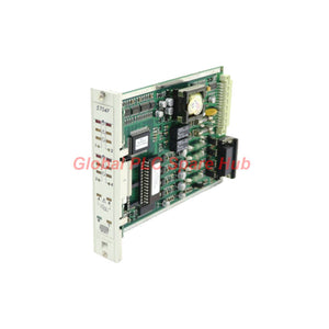
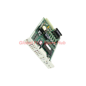
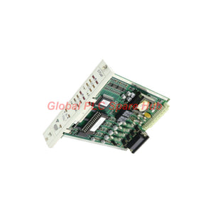
05704-A-0146 Honeywell 5704F Series Fire Alarm Control Card
Manufacturer: Honeywell
Product No.: 05704-A-0146
Condition: In stock
Product Type: Fire Detection Control
Product Origin: USA
Payment: T/T, Western Union
Weight: 160g
Shipping port: Xiamen
Warranty: 12 months
Estimate delivery times: 12-26 days (International), 3-6 days (United States).
Return within 30 days of purchase. Duties & taxes are non-refundable.
Guaranteed Safe Checkout
Product Overview | Four-Channel Fire Detection Control
Honeywell 05704-A-0146, identified as the 5704F Fire Control Card, provides control, display, and alarm functions for up to four independent fire detection loops or zones.
The card supplies the required drive voltages and currents for connected sensors, processes incoming signals, and compares each loop against configured alarm and fault limits. When a defined threshold is exceeded, it activates the corresponding front-panel indications and configured relay or switched DC outputs.
Microprocessor-controlled operation supports configurable detector types and application requirements. Setup information is stored in non-volatile memory on the card. User-selectable jumper links provide additional configuration options for supported system requirements.
The 5704F integrates the stated fire control functions on a single card, without requiring additional plug-in modules for the common applications described in the manufacturer documentation. Actual system suitability depends on the installed fire detection architecture and configuration.
System Function Map
| Functional Area | Specified Capability | Engineering Purpose |
|---|---|---|
| Fire Detection Inputs | 4 fire zone inputs | Monitor up to four separate detection loops or zones. |
| Sensor Interface | Provides required sensor drive voltages and currents | Supports compatible detectors connected to each loop. |
| Signal Processing | Microprocessor-controlled input processing | Evaluates incoming sensor signals against configured limits. |
| Alarm and Fault Logic | Predefined alarm and fault thresholds | Distinguishes configured alarm and fault conditions. |
| Switched DC Outputs | 2 fault-monitored switched DC outputs | Provides configured output functions with fault monitoring. |
| Remote Input | 1 three-function remote input | Supports the remote functions defined by the installed system configuration. |
| Relay Outputs | Up to 16 configurable relay outputs | Supports system-specific alarm and status signaling. |
| System Communication | Reports input status information to other cards | Shares detection status with compatible system cards. |
| Self-Validation | Checks circuit components, software operation, loop inputs, remote input, and switched DC outputs | Supports fault detection within the card's specified monitoring scope. |
Product Identification and Physical Data
| Parameter | Specification |
|---|---|
| Manufacturer | Honeywell |
| Part Number | 05704-A-0146 |
| Product Model | 5704F |
| Product Type | Four-channel fire control card |
| Fire Detection Capacity | 4 loops or zones |
| Switched DC Outputs | 2, fault-monitored |
| Remote Input | 1, three-function |
| Configurable Relay Outputs | Up to 16 |
| Dimensions (L × W × H) | 172 × 25 × 132 mm |
| Weight | 0.16 kg |
| Configuration Storage | Non-volatile memory on the fire card |
| Configuration Options | User-selectable jumper links |
Front-Panel Indication | Reading the Card Status
The front panel uses LEDs to show the status of each detection zone, output faults, and overall card conditions. Use these indicators as the first diagnostic reference, then verify the underlying loop or output circuit.
| Indicator Group | LED Color | Indicated Status |
|---|---|---|
| Fire, per zone | Red | Fire indication for the corresponding zone. |
| Fault, per zone | Amber | Fault indication for the corresponding detection zone. |
| Inhibit, per zone | Amber | Zone inhibit indication. |
| Select, per zone | Amber | Zone selection indication. |
| Output fault | Amber | Fault indication associated with an output. |
| Power | Green | Power status indication. |
| Call Engineer | Amber | Engineering attention indication. |
A lit LED identifies a reported condition; it does not by itself prove the cause. Interpret each indication using the original 5704F operating documentation and the configured system logic.
Typical System Applications
- Industrial fire detection panels: Monitor up to four compatible fire detection loops or zones.
- Process plant safety installations: Provide configured fire detection control and status signaling within an approved system design.
- Equipment and utility areas: Collect detection signals from compatible devices installed in defined protection zones.
- Multi-zone detection systems: Process zone inputs and report alarm or fault status to other compatible system cards.
- Fire system maintenance and repair: Replace a matching card after verifying the part number, configuration, and installed system requirements.
The number and type of detectors supported by each loop depend on the detector characteristics and system design. Confirm loop loading, detector compatibility, and alarm thresholds against the applicable manufacturer documentation.
Global PLC Spare HUB's Insight | Field Diagnostics
Case 1 — A zone displays a fault indication. Identify the affected zone and inspect its detector loop, wiring continuity, field device condition, and configured fault threshold. Compare measured loop conditions with the detector and controller specifications before replacing the card.
Case 2 — A detector event does not trigger the expected alarm. Verify the detector's output behavior, loop signal, configured alarm threshold, and card configuration. Confirm that the intended relay or switched DC output is assigned and operating according to the system design.
Case 3 — An output fault LED appears. Identify the associated output and inspect the external wiring, connected load, and output circuit condition. Since the card provides fault-monitored switched DC outputs, compare the observed behavior with the documented monitoring method.
Case 4 — The card reports a condition after replacement. Verify the complete part number, stored setup information, jumper-link positions, detector compatibility, and system configuration. A replacement card may require configuration checks before its behavior matches the original installation.
Case 5 — The Call Engineer indicator is active. Record all zone and output indications before changing any settings. Consult the applicable troubleshooting procedure to determine whether the condition relates to an input, output, configuration, or internal card check.
Case 6 — The front panel indicates normal power, but field operation is abnormal. Do not rely on the power LED alone. Test the relevant detection loop and configured output path, then compare the results with the system's documented alarm and fault logic.
Recommended diagnostic record: Record the part number, affected zone, LED states, detector type, loop measurements, output status, jumper settings, and recent maintenance changes. This information helps engineers isolate the fault without making unsupported assumptions about the card's condition.
Replacement and Configuration Checklist
- Confirm identification: Match part number 05704-A-0146 and model 5704F against the installed card.
- Verify system compatibility: Check the host system, rack or mounting arrangement, companion cards, and documented hardware requirements.
- Record the existing configuration: Document detector types, alarm and fault thresholds, jumper-link positions, and output assignments.
- Inspect field connections: Check loop wiring, remote input wiring, relay circuits, and switched DC output connections.
- Review stored setup: Confirm the configuration required for the application and verify it using approved procedures.
- Test each zone: Conduct approved functional tests for alarm, fault, inhibit, and other configured indications.
- Verify output operation: Check the required relay and switched DC outputs using the system's documented test procedure.
- Document commissioning: Record test results and confirm the system is returned to its approved operating state.
Frequently Asked Questions
Q1: What information is most useful when ordering a replacement fire control card?
A: Provide the complete part number, the installed system model, companion card details, detector types, and any available configuration records. A clear nameplate photograph and front-panel photograph can help confirm identification before ordering.
Q2: Does four-channel capacity mean that only four detectors can be connected?
A: No. The card supports four separate loops or zones, and a loop may support more than one detector depending on detector type and loop design. Confirm allowable detector quantities and electrical loading in the relevant system documentation.
Q3: Should the jumper links be copied from the old card during replacement?
A: Record the existing positions as a reference, but verify them against the required configuration and manufacturer instructions. The correct setting depends on the connected detectors and system requirements; copying an unknown or incorrect setup can preserve an existing fault.
Q4: How should engineers investigate an alarm output that fails during testing?
A: Trace the complete path from the zone input through the configured alarm logic to the assigned relay or switched DC output. Check the output wiring and connected circuit, then verify the card's configuration and fault indications using the approved test procedure.
Q5: Can this card be considered a standalone replacement for any four-zone fire alarm controller?
A: No. The 5704F is a system card with defined interfaces and configuration requirements. Verify the host system, detector compatibility, output requirements, companion cards, and applicable safety documentation before selecting it as a replacement.
Warranty, Packaging and Shipping
- Product: Honeywell 5704F Four-Channel Fire Control Card.
- Part Number: 05704-A-0146.
- Warranty: 12-month warranty, subject to the supplier's applicable warranty terms.
- Shipping Methods: FedEx, UPS, and DHL, subject to destination and service availability.
- Packaging: Protective packaging suitable for transport. Confirm any special handling or packaging requirements when requesting a quotation.
- Order Verification: Provide the part number and installed system details to support compatibility checks before purchase.
Request a Quote: Contact Global PLC Spare HUB for pricing, availability, shipping options, and assistance verifying the Honeywell 05704-A-0146 fire control card against your existing system.
Safety Notice: Fire detection and alarm equipment forms part of a safety-related installation. Installation, configuration, testing, and replacement must be performed by qualified personnel under approved procedures. Do not return the system to service until required functional tests have been completed and documented.

Tags
Q: Are these parts 100% original and new?
A: Yes. Every component is guaranteed to be 100% original, brand-new, and factory-sealed. We also provide a 12-month comprehensive warranty for your peace of mind.
Q: How fast is the shipping to my country?
A: For in-stock items, we offer same-day dispatch. International express shipping (DHL/FedEx/UPS) typically delivers within 3–5 business days worldwide.
Q: Can I get a formal quotation with shipping costs?
A: Absolutely. Our sales team is ready to provide a detailed Proforma Invoice (PI) including the most competitive shipping rates for your location.
Q: Do you offer discounts for bulk orders?
A: We provide volume-based pricing for large projects or multiple-item orders. Please contact us to get our Best Price Guarantee.
12-Month Comprehensive Warranty
Every part supplied by Global PLC Spare Hub is covered by a 12-month warranty from the date of invoice.
- Coverage: Functional defects and hardware failures under normal operating conditions.
- Commitment: We provide immediate repair, replacement, or a full refund for any verified defective components to minimize your operational downtime.
Returns & Exchange Policy
We offer a 30-day return policy to ensure you receive the exact part your system requires.
- Eligibility: Returns are accepted for uninstalled items in their original, factory-sealed packaging.
- RMA Process: Please contact our support team to obtain a Return Merchandise Authorization (RMA) number before shipping.
- Fast Processing: Refunds or exchanges are processed within 3–5 business days after the returned item passes our technical inspection.
Need Technical Assistance?Not sure if this part is compatible with your system? [Consult our Engineers] before purchasing to ensure 100% compatibility.
People Also Bought


