


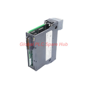

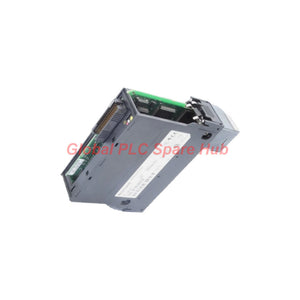
TC-IXL061 Honeywell Temperature Input I/O Module
Manufacturer: Honeywell
Product No.: TC-IXL061
Condition: In stock
Product Type: Thermocouple Input Module
Product Origin: USA
Payment: T/T, Western Union
Weight: 500g
Shipping port: Xiamen
Warranty: 12 months
Estimate delivery times: 12-26 days (International), 3-6 days (United States).
Return within 30 days of purchase. Duties & taxes are non-refundable.
Guaranteed Safe Checkout
Honeywell TC-IXL061 Thermocouple Input Module
The Honeywell TC-IXL061 is a six-point thermocouple input module designed to acquire temperature-related millivolt signals from industrial thermocouples. It supports nine thermocouple types and provides a dedicated cold junction (CJ) channel for reference-junction compensation.
With 16-bit resolution, a 50 ms update rate across all channels, and configurable measurement ranges, the TC-IXL061 supports temperature monitoring in process control systems where signal integrity, sensor diagnostics, and measurement consistency are important. Its 20-position TC-TBNH terminal block provides the field connection interface.
Replacement note: The TC-IXL061 has been superseded by the TC/TK-IXL062 according to the supplied product information. The replacement requires terminal-block rewiring. Applications using an RTP also require a new pre-wired cable. Confirm the exact module designation and wiring documentation before ordering or beginning a retrofit.
Technical Specifications
| Parameter | Specification |
|---|---|
| Manufacturer | Honeywell |
| Model | TC-IXL061 |
| Module Type | Thermocouple input module |
| Input Channels | 6 thermocouple channels plus 1 cold junction channel |
| Standard Input Range | -12 mV to +78 mV |
| High-Resolution Input Range | -12 mV to +30 mV |
| Supported Thermocouple Types | B, E, J, K, R, S, T, N, C |
| Resolution | 16 bits; 1.4 µV typical; 0.70 µV on the high-resolution range |
| Accuracy, Standard Range at 25°C | 0.1% FSR ±90 µV |
| Accuracy, High-Resolution Range at 25°C | 0.1% FSR ±42 µV |
| Local Cold Junction Sensor Error | ±0.3°C to ±3.0°C, depending on channel |
| Remote Cold Junction Sensor Error | ±0.3°C |
| All-Channel Update Rate | 50 ms |
| Settling Time to 5% of Full Scale | Less than 80 ms |
| Open-Thermocouple Detection | Typically 5 seconds; upscale reading |
| Channel Bandwidth | 0 to 15 Hz (-3 dB) |
| Common-Mode Rejection | 120 dB at 60 Hz; 100 dB at 50 Hz |
| Normal-Mode Noise Rejection | 60 dB at 60 Hz |
| RFI Immunity | Error below 2.0% of range at 10 V/m, 27–1000 MHz |
| Continuous Overvoltage Capability | 120 VAC/VDC at 25°C |
| Input Offset Drift | 0.5 µV/°C typical |
| Gain Drift | 65 ppm/°C typical |
| Maximum Power Dissipation | 4.3 W |
| Spare CJ Thermistor | TC-CJRT01, part number 51109433-100 |
| Terminal Block | TC-TBNH, 20-position |
| Channel-to-Channel Isolation | 100% tested at 2546 VDC for 1 second |
| User-to-System Isolation | 100% tested at 2546 VDC for 1 second |
FSR means full-scale range. Backplane current should be checked against the applicable Honeywell module power-consumption documentation. Verify all specifications against the manual for the installed hardware revision.
Measurement Architecture: Six Inputs and Cold Junction Compensation
The TC-IXL061 measures the millivolt signal generated by each connected thermocouple. Since thermocouple voltage depends on the temperature difference between the measuring junction and the reference junction, reliable temperature calculation also requires cold junction compensation.
- Six measurement channels: Acquire temperature signals from separate process points, subject to the configured thermocouple type and input range.
- Cold junction channel: Provides the reference information needed for thermocouple compensation. The installed configuration determines whether local or remote compensation applies.
- High-resolution range: The -12 mV to +30 mV range provides a specified resolution of 0.70 µV. Confirm that the expected sensor signal remains within the selected range.
- Input noise rejection: Common-mode and normal-mode rejection specifications help engineers assess signal quality in electrically noisy cabinets.
- Open-sensor detection: The module typically detects an open thermocouple in 5 seconds and reports an upscale reading.
An upscale reading should be treated as a diagnostic indication rather than proof of an open sensor. Confirm the channel status, field wiring, sensor continuity, and configured thermocouple type before making a maintenance decision.
Global PLC Spare HUB's Insight
For maintenance engineers, the main selection issue is not simply the number of thermocouple inputs. The configured sensor type, cold junction arrangement, wiring method, and replacement interface all affect the validity of the temperature value delivered to the control application.
- Check sensor configuration: Verify whether each field sensor is Type B, E, J, K, R, S, T, N, or C. An incorrect type selection can produce plausible but inaccurate temperature readings.
- Investigate channel-to-channel differences: If similar process points show unexpected offsets, compare sensor type, polarity, terminal condition, cable routing, and cold junction conditions before replacing the module.
- Separate sensor faults from input faults: Inspect the thermocouple and extension wiring first. If the fault persists, compare the affected channel with a known-good channel using an approved test procedure.
- Review the installation enclosure: The supplied guidance recommends a NEMA 4 or NEMA 12 enclosure approximately 610 mm wide, 508 mm high, and 203 mm deep to maintain approximately ±3°C reference-junction compensation. Confirm the applicable manual and installation conditions before treating this enclosure dimension as a universal requirement.
- Plan replacements before shutdown: The TC/TK-IXL062 replacement requires terminal-block rewiring, and RTP installations require a new pre-wired cable. Include wiring drawings, cable procurement, configuration checks, and post-installation validation in the maintenance plan.
Suitable Equipment and Industrial Applications
| Application Area | Typical Measurement Points | Engineering Consideration |
|---|---|---|
| Process manufacturing | Heated vessels, process lines, and thermal stages | Match the thermocouple type and input range to the expected temperature signal. |
| Furnaces and thermal equipment | Heating zones and temperature profiles | Confirm sensor suitability, range limits, and cold junction compensation requirements. |
| Utilities and energy systems | Equipment temperatures and thermal process monitoring | Check noise exposure, cable routing, and measurement response requirements. |
| Industrial machinery | Motor, bearing, or process-equipment temperature points where thermocouples are specified | Verify that the selected sensor and control-system design support the intended measurement. |
| Control-system maintenance | Existing six-point thermocouple input installations | Confirm hardware revision, terminal-block wiring, and replacement cable requirements. |
These are potential application areas for thermocouple input modules, not a claim that every listed installation is compatible with the TC-IXL061. Confirm the target Honeywell control platform and approved module configuration before installation.
Diagnostic Guide for Field Engineers
| Observed Symptom | Possible Cause | Recommended Checks |
|---|---|---|
| Upscale reading on one channel | Open thermocouple, loose terminal, broken extension wire, or connection fault | Inspect field wiring and terminal tightness; verify continuity and channel status. |
| Temperature offset across multiple channels | Incorrect sensor-type configuration, cold junction issue, or common wiring error | Compare configured sensor types, polarity, terminal conditions, and CJ configuration. |
| Unstable readings near electrical equipment | Electromagnetic interference, poor shielding, or unsuitable cable routing | Inspect cable routing and grounding practices; separate low-level sensor wiring from power conductors where required. |
| Unexpected clipping or out-of-range values | Input range mismatch or sensor signal outside the configured range | Compare the expected thermocouple millivolt signal with the selected range and configuration. |
| Temperature changes after module replacement | Different terminal wiring, sensor configuration, or cold junction arrangement | Compare as-built wiring and configuration records with the replacement module documentation. |
| Several channels fail after a retrofit | Terminal-block rewiring error, incorrect cable, or configuration mismatch | Stop relying on the affected readings until wiring, channel mapping, and system status are verified. |
Diagnostic caution: The open-thermocouple function typically takes 5 seconds. A normal reading during this interval does not necessarily rule out an intermittent wiring fault. Use the control-system diagnostics and an approved sensor test procedure to confirm the cause.
Installation and Commissioning Checklist
- Verify the hardware: Confirm the TC-IXL061 model, module revision, terminal block, and control-system compatibility from the applicable documentation.
- Check field sensor assignments: Record the thermocouple type, channel number, polarity, and expected operating range for each input.
- Inspect the reference junction: Verify the local or remote cold junction arrangement and the associated sensor or thermistor configuration.
- Check the terminal interface: Confirm the TC-TBNH 20-position terminal block and ensure that field connections match the approved wiring diagram.
- Validate the enclosure: Review enclosure rating, dimensions, ambient conditions, and the manufacturer's installation recommendations for reference-junction compensation.
- Test before returning to service: Confirm channel mapping, plausible readings, open-sensor diagnostics, and control-system alarm behavior under the approved commissioning procedure.
- Document the result: Record sensor types, configuration values, wiring changes, measured offsets, and any replacement-related adjustments.
Follow the plant's lockout/tagout procedures and applicable electrical safety rules before handling field wiring. Do not disconnect or test live circuits unless the approved procedure explicitly permits it.
Replacement Planning: TC-IXL061 to TC/TK-IXL062
The TC-IXL061 is identified in the supplied information as superseded by the TC/TK-IXL062. Because a replacement may involve interface changes, confirm the exact ordering code before purchasing.
- Compare the installed module label with the requested replacement part number.
- Obtain the correct terminal-block wiring information for the replacement module.
- If an RTP is installed, confirm and order the required replacement pre-wired cable.
- Verify thermocouple channel mapping, cold junction configuration, and control-system support.
- Plan a controlled commissioning test before returning temperature-dependent control functions to normal operation.
Do not assume that matching channel counts guarantee plug-and-play compatibility. The replacement decision should be based on the hardware revision, system documentation, wiring interface, and approved configuration.
Frequently Asked Questions
Q1. What information should be provided when requesting a quotation for the TC-IXL061?
Provide the full model number, any available part number, the installed control-system platform, the required quantity, and whether the purchase is for an existing installation or a planned retrofit. If replacing an installed unit, include the terminal-block and RTP details so the replacement requirements can be reviewed.
Q2. How should engineers evaluate a temperature reading that is stable but consistently different from a reference instrument?
First compare the reference instrument's sensor type, calibration status, measurement location, and response characteristics. Then check the TC-IXL061 channel configuration, cold junction compensation, terminal temperature conditions, and wiring polarity. A stable offset does not by itself prove that the input module is defective.
Q3. Is the high-resolution input range automatically the best choice for every thermocouple?
No. The -12 mV to +30 mV range offers finer specified voltage resolution, but the expected sensor signal must remain within that range. Select the input range using the thermocouple type and expected operating conditions, and verify the configured range against the Honeywell documentation.
Q4. What should be checked before using a spare cold junction thermistor?
Confirm that the required component is TC-CJRT01, part number 51109433-100, and verify that the installed module configuration supports the intended cold junction arrangement. Check the connection method and the applicable installation instructions before fitting a spare part.
Q5. What documentation should be retained after replacing the TC-IXL061?
Keep the original and replacement part numbers, module revision details, revised terminal wiring, any RTP cable part number, channel-to-sensor mapping, configuration records, and commissioning results. These records help the next maintenance team distinguish a hardware problem from a wiring or configuration change.
Ordering, Warranty and Logistics
- Product: Honeywell TC-IXL061 Thermocouple Input Module
- Technical confirmation: Contact Global PLC Spare HUB with the complete model number and application details.
- Warranty: 12-month warranty, subject to the supplier's applicable terms and conditions.
- Shipping options: FedEx, UPS, or DHL, subject to destination and shipment arrangements.
- Replacement support: Confirm terminal-block rewiring and RTP cable requirements before ordering a TC/TK-IXL062 replacement.
Request a quotation: Contact Global PLC Spare HUB to confirm model identification, replacement requirements, pricing, and shipping options for the Honeywell TC-IXL061.
Tags
Q: Are these parts 100% original and new?
A: Yes. Every component is guaranteed to be 100% original, brand-new, and factory-sealed. We also provide a 12-month comprehensive warranty for your peace of mind.
Q: How fast is the shipping to my country?
A: For in-stock items, we offer same-day dispatch. International express shipping (DHL/FedEx/UPS) typically delivers within 3–5 business days worldwide.
Q: Can I get a formal quotation with shipping costs?
A: Absolutely. Our sales team is ready to provide a detailed Proforma Invoice (PI) including the most competitive shipping rates for your location.
Q: Do you offer discounts for bulk orders?
A: We provide volume-based pricing for large projects or multiple-item orders. Please contact us to get our Best Price Guarantee.
12-Month Comprehensive Warranty
Every part supplied by Global PLC Spare Hub is covered by a 12-month warranty from the date of invoice.
- Coverage: Functional defects and hardware failures under normal operating conditions.
- Commitment: We provide immediate repair, replacement, or a full refund for any verified defective components to minimize your operational downtime.
Returns & Exchange Policy
We offer a 30-day return policy to ensure you receive the exact part your system requires.
- Eligibility: Returns are accepted for uninstalled items in their original, factory-sealed packaging.
- RMA Process: Please contact our support team to obtain a Return Merchandise Authorization (RMA) number before shipping.
- Fast Processing: Refunds or exchanges are processed within 3–5 business days after the returned item passes our technical inspection.
Need Technical Assistance?Not sure if this part is compatible with your system? [Consult our Engineers] before purchasing to ensure 100% compatibility.
People Also Bought


