


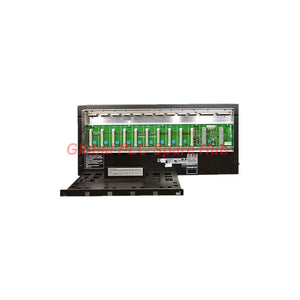

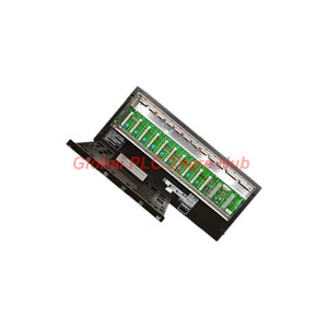
SNB10D-225/CU2T Yokogawa Safety Node Unit | Redundant Power
Manufacturer: Yokogawa
Product No.: SNB10D-225/CU2T
Condition: متوفر بالمخزون
Product Type: Safety Node Unit
Product Origin: SG
Payment: T/T, Western Union
Weight: 5900g
Shipping port: Xiamen
Warranty: 12 months
تقدير أوقات التسليم: 12-26 يومًا (دوليًا)، 3-6 أيام (الولايات المتحدة).
يجب الإرجاع خلال 30 يومًا من الشراء. الرسوم والضرائب غير قابلة للاسترداد.
دفع آمن ومضمون
Yokogawa SNB10D-225/CU2T | Safety Node Unit Overview
The Yokogawa SNB10D-225/CU2T is a rack-mounted safety node unit designed for compatible Yokogawa safety control systems. It provides the hardware platform for installing supported field input/output modules and connecting them to the safety control unit through an ESB bus interface. This configuration combines dual-redundant power supply modules, two SSB401 ESB bus interface modules, and a CU2T connector unit with an ESB bus terminator. Its specified power input is 220–240 V AC at 50/60 Hz. The unit supports safety system expansion through compatible safety control units and ESB bus couplers. Engineers must verify node limits, I/O slot restrictions, and the approved system configuration before installation.
Technical Specifications
| Manufacturer | Yokogawa |
| Model | SNB10D-225/CU2T |
| Product Series | SNB10D |
| Product Type | Safety Node Unit |
| Mounting Method | Rack mounting with four M5 screws and insulation bushes |
| Power Supply Configuration | Dual-redundant power supply |
| Rated Input Voltage | 220–240 V AC |
| Input Frequency | 50/60 Hz |
| Power Consumption | 230 VA for the 220–240 V AC version |
| Power Supply Modules | Two modules |
| ESB Bus Interface Modules | Two SSB401 modules |
| Connector Unit | CU2T with ESB bus terminator |
| Connector Unit Part Number | S9343FA |
| Environmental Specification | ISA Standard G3 |
| Specified Temperature Range | -20°C to +70°C |
| Explosion Protection | Not included in this suffix configuration |
| Power Supply Terminal | M4 screw terminals |
| Weight | Approximately 5.9 kg |
| Warranty | 12 months, subject to seller terms |
Model Suffix and Configuration Breakdown
| Code | Meaning |
| SNB10D | Rack-mounted safety node unit model |
| -2 | Dual-redundant power supply with software license for node expansion (R3) |
| -2 | 220–240 V AC power supply specification |
| -5 | ISA Standard G3, -20°C to +70°C, without explosion protection |
| /CU2T | Connector unit with ESB bus terminator |
| S9343FA | Part number associated with the CU2T connector unit |
Confirm the complete designation SNB10D-225/CU2T before ordering. The suffixes identify important differences in power configuration, environmental requirements, and bus termination hardware.
Internal Architecture and Functional Roles
The node unit combines power distribution, bus communication, and I/O mounting within a rack-mounted assembly.
- Dual power supply modules: Two modules supply power to the installed I/O modules. The redundant arrangement supports the intended power architecture, subject to the system design.
- SSB401 ESB bus interfaces: Two interface modules provide the specified ESB bus interface hardware.
- CU2T connector unit: Provides the ESB bus termination function for the configured connection.
- I/O module mounting positions: Accommodate supported modules according to Yokogawa's slot and quantity restrictions.
- Rack mounting hardware: Uses four M5 screws and insulation bushes for installation.
The exact supported I/O combination depends on the system configuration. Consult the applicable Yokogawa documentation before assigning modules to individual slots.
Safety Control System Compatibility and Node Expansion
The documented maximum number of connectable safety node units depends on the ESB bus coupler and safety control unit configuration.
| ESB Bus Coupler | Referenced Safety Control Units | Maximum Connectable Safety Nodes |
| SEC402 | S2SC70S, S2SC70D, SSC60S, SSC60D | Up to 13 |
| SEC401 | Compatible safety control unit configuration | Up to 9 |
These limits describe the supplied configuration information. They do not guarantee that every installation can use the maximum node count. Verify controller capacity, bus topology, software licensing, and project-specific hardware restrictions.
Typical Industrial Applications
- Process safety systems: Provides a node platform for supported safety I/O modules in process automation installations.
- Oil and gas facilities: Supports distributed safety control architectures when the selected controller and I/O configuration meet project requirements.
- Chemical processing: Houses compatible I/O modules for safety-related field signal interfaces.
- Power generation: Supports safety control node expansion in compatible plant control systems.
- Industrial plant upgrades: Provides a replacement or expansion option when the installed system requires the same node configuration.
The node unit does not independently define the complete safety function. System-level performance depends on the controller, I/O modules, configuration, application logic, and approved engineering design.
Installation and Commissioning Guide
1. Verify the supply configuration Confirm the full model number and the 220–240 V AC power specification. Check the cabinet supply and protective measures before connecting power. 2. Prepare the rack installation Secure the unit using four M5 screws and the specified insulation bushes. Confirm that the mounting arrangement meets the equipment documentation and cabinet requirements. 3. Inspect the power supply modules Verify the presence and seating of both power supply modules. Check their M4 screw terminals and follow the approved wiring instructions. 4. Check the ESB bus interfaces Confirm the installation of both SSB401 interface modules. Inspect the ESB bus connections and verify the CU2T connector unit and terminator arrangement. 5. Review I/O slot restrictions Do not populate every slot based solely on physical availability. Yokogawa defines module quantity and slot-position restrictions for safety node units. Consult document GS 32P06K60-01EN, including its section on node unit mounting restrictions. 6. Validate system configuration Confirm the selected safety controller, ESB coupler, node count, and node expansion license. Verify the configured topology before energizing the complete system. 7. Complete commissioning checks Follow the approved startup procedure. Check power status, module recognition, ESB communication, and I/O diagnostics through the supported engineering tools. Resolve active faults before releasing the system for operation.
Diagnostics and Field Maintenance
When a safety node fails to start or communicate, troubleshoot the shared infrastructure before replacing individual I/O modules.
- Node fails to start: Verify the incoming AC supply, protection devices, power wiring, and seating of both power supply modules.
- ESB communication fault: Inspect the SSB401 interfaces, bus connections, CU2T terminator, and configured topology.
- New node is not recognized: Check the node expansion license, controller compatibility, coupler capacity, and system configuration.
- I/O module is not recognized: Confirm the module's approved slot position and quantity restrictions. Inspect the module seating and diagnostic status.
- Intermittent node faults: Review power stability, rack connections, bus connector seating, and environmental conditions.
- Repeated faults after replacement: Compare the replacement's suffix codes, power rating, interface configuration, and firmware or hardware requirements.
Field example: A newly installed safety node fails to appear in the controller configuration. Check the ESB coupler's node capacity and expansion license first. Then inspect the SSB401 interfaces, CU2T termination, and bus connections. Finally, verify the node configuration in the engineering system before considering component replacement. Maintenance teams should record node identifiers, active diagnostic codes, power measurements, and changes to bus connections. Follow approved safety procedures when inspecting or servicing an energized control system.
Environmental and Safety Considerations
The SNB10D-225/CU2T specifies ISA Standard G3 environmental resistance and an operating temperature range of -20°C to +70°C. Confirm the installation environment against the manufacturer's requirements. The -5 suffix configuration does not include explosion protection. Do not use this designation alone as evidence of hazardous-area approval. The supplied information identifies the unit as a safety node but does not provide a complete SIL certification statement for this exact assembly. Verify the applicable safety manuals, certificates, controller architecture, and approved I/O configuration before using it in a safety instrumented function.
Global PLC Spare HUB's Insight
The Yokogawa SNB10D-225/CU2T should be selected as a complete node configuration, not simply as a rack with redundant power. The ESB interface arrangement, termination hardware, power specification, and node expansion license all affect integration. In a plant expansion project, an available rack position does not automatically mean that another safety node can be added. The engineer must check the selected SEC401 or SEC402 coupler, controller capacity, software licensing, and permitted node count. The I/O slot restrictions also require review before loading the rack. For replacement work, compare the existing unit's full model code and connector arrangement. Confirm that the new assembly uses the required 220–240 V AC supply and CU2T terminator. These checks help avoid configuration mismatches during commissioning. Our recommendation is to confirm the controller model, ESB coupler, required I/O modules, and safety documentation before requesting a quotation. This produces a more reliable compatibility assessment than using the product family name alone.
Packaging, Shipping, and Warranty
Product configuration:
- Yokogawa SNB10D-225/CU2T Safety Node Unit.
- Specified internal configuration includes two power supply modules and two SSB401 ESB bus interface modules.
- CU2T connector unit with ESB bus terminator, associated with part number S9343FA.
- Mounting accessories and additional items should be confirmed against the sales quotation.
Warranty: 12 months, subject to the seller's written terms. Shipping options: FedEx, UPS, and DHL. Dispatch target: 24–48 hours after order processing, subject to stock confirmation and shipping arrangements. Contact Global PLC Spare HUB to confirm availability, exact configuration, shipping arrangements, and quotation details.
Frequently Asked Questions
Q1: Can I add another safety node if the existing rack has unused space? Not necessarily. Confirm the ESB coupler limit, controller capacity, node expansion license, bus topology, and I/O slot restrictions. Physical space alone does not establish system compatibility.
Q2: What should I verify when changing from a SEC401 to a SEC402 coupler? Review the supported controller configuration, maximum node count, bus topology, software licensing, and applicable system documentation. Do not assume that a coupler change requires no engineering or configuration updates.
Q3: Does the dual-redundant power configuration guarantee uninterrupted operation? No hardware configuration can guarantee uninterrupted operation under every fault condition. Confirm the system's redundancy design, power supply status monitoring, load requirements, and manufacturer-defined failure behavior.
Q4: How should I investigate repeated ESB communication alarms after maintenance? Check the bus topology, connector seating, termination arrangement, and SSB401 module status. Compare the physical installation with the approved system drawings before changing configuration settings.
Q5: What information should I provide to select a compatible replacement? Provide the complete model number, safety controller model, SEC401 or SEC402 coupler type, existing node count, required I/O modules, and supply voltage. Include the current ESB termination arrangement and any applicable safety certification requirements.

Tags
س: هل هذه الأجزاء أصلية وجديدة 100%؟
ج: نعم. نضمن أن كل مكون هو أصلي 100%، وجديد تمامًا، ومغلف من المصنع. كما نقدم ضمانًا شاملاً لمدة 12 شهرًا لراحتك.
س: ما مدى سرعة الشحن إلى بلدي؟
ج: بالنسبة للعناصر المتوفرة في المخزون، نقدم إرسالاً في نفس اليوم. وعادةً ما يتم التسليم عبر الشحن السريع الدولي (DHL/FedEx/UPS) في غضون 3-5 أيام عمل في جميع أنحاء العالم.
س: هل يمكنني الحصول على عرض أسعار رسمي يشمل تكاليف الشحن؟
ج: بالتأكيد. فريق المبيعات لدينا مستعد لتقديم فاتورة مبدئية (PI) مفصلة تتضمن أسعار الشحن الأكثر تنافسية لموقعك.
س: هل تقدمون خصومات للطلبات الكبيرة؟
ج: نقدم أسعارًا تعتمد على الحجم للمشاريع الكبيرة أو طلبات العناصر المتعددة. يرجى الاتصال بنا للحصول على ضمان أفضل الأسعار لدينا.
ضمان شامل لمدة 12 شهرًا
كل جزء توفره Global PLC Spare Hub مشمول بـ ضمان لمدة 12 شهرًا من تاريخ الفاتورة.
- التغطية: عيوب وظيفية وأعطال في الأجهزة في ظل ظروف التشغيل العادية.
- التزامنا: نقدم إصلاحًا فوريًا أو استبدالًا أو استردادًا كاملاً لأي مكونات معيبة تم التحقق منها لتقليل وقت التوقف التشغيلي لديك.
سياسة الإرجاع والاستبدال
نقدم سياسة إرجاع لمدة 30 يومًا لضمان حصولك على الجزء الدقيق الذي يتطلبه نظامك.
- الأهلية: تُقبل المرتجعات للعناصر غير المركبة في تغليفها الأصلي والمحكم الإغلاق من المصنع.
- عملية RMA: يرجى الاتصال بفريق الدعم لدينا للحصول على رقم ترخيص إرجاع البضائع (RMA) قبل الشحن.
- معالجة سريعة: تتم معالجة المبالغ المستردة أو الاستبدالات في غضون 3-5 أيام عمل بعد أن يجتاز العنصر المرتجع فحصنا الفني.
هل تحتاج إلى مساعدة فنية؟لست متأكدًا مما إذا كان هذا الجزء متوافقًا مع نظامك؟ [استشر مهندسينا] قبل الشراء لضمان التوافق بنسبة 100%.
اشترى الناس أيضًا


