


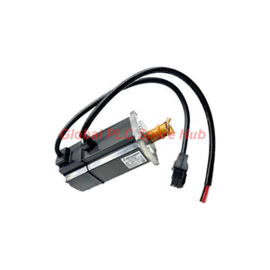
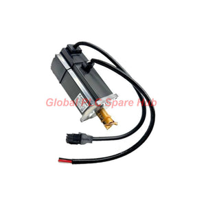
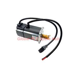
TLP-B200-300-DJMD2A Allen-Bradley TL-Series 3.0 kW Servo Motor
Manufacturer: Allen-Bradley
Product No.: TLP-B200-300-DJMD2A
Condition: In stock
Product Type: Servo Motor
Product Origin: USA
Payment: T/T, Western Union
Weight: 500g
Shipping port: Xiamen
Warranty: 12 months
Estimate delivery times: 12-26 days (International), 3-6 days (United States).
Return within 30 days of purchase. Duties & taxes are non-refundable.
Guaranteed Safe Checkout
Allen-Bradley TLP-B200-300-DJMD2A Kinetix TL-Series Servo Motor
The TLP-B200-300-DJMD2A is an Allen-Bradley Kinetix TL-Series servo motor designed for industrial motion-control systems that require controlled torque and repeatable positioning. Its 400 V class design, 3.0 kW rating, and 28.7 N·m continuous stall torque make it a candidate for demanding automated machinery.
This configuration combines a 200 mm bolt-circle frame, a 24-bit single-turn absolute encoder with multi-turn capability requiring a battery, and a keyed shaft. It has no holding brake and uses the standard shaft configuration without a shaft seal. Verify the complete motor code and drive compatibility before ordering.
01 | Configuration at a Glance
| Manufacturer | Allen-Bradley |
|---|---|
| Product Series | Kinetix TL-Series |
| Model | TLP-B200-300-DJMD2A |
| Product Type | TL-Series Servo Motor |
| Voltage Class | 400 V AC class |
| Rated Power | 3.0 kW |
| Continuous Stall Torque | 28.7 N·m |
| Frame Size | 200 mm bolt-circle frame |
| Feedback Device | 24-bit single-turn absolute encoder; multi-turn operation requires a battery |
| Shaft Configuration | Keyed shaft |
| Holding Brake | Not included in the specified configuration |
| Shaft Seal | Standard configuration without shaft seal |
02 | Model Code and Configuration Breakdown
| Code | Configuration Meaning | Selection Consideration |
|---|---|---|
| TLP | TL-Series servo motor family | Confirm that the intended servo drive supports this motor family and feedback interface. |
| B | 400 V AC class | Match the motor voltage class to the selected drive and facility power architecture. |
| 200 | 200 mm bolt-circle frame size | Check mounting dimensions, flange clearance, and mechanical alignment. |
| 300 | 3.0 kW motor rating in the supplied model description | Evaluate the complete speed-torque curve, load inertia, and duty cycle. |
| D | 24-bit single-turn absolute encoder; multi-turn capability requires a battery | Confirm encoder support, battery requirements, and position-retention behavior with the drive documentation. |
| J | Keyed shaft | Match the coupling or pulley bore and key dimensions to the motor shaft. |
| A | Standard configuration without shaft seal | Assess exposure to dust, moisture, oil, and other contaminants at the installation point. |
Ordering note: The breakdown above follows the supplied model description. Confirm the complete catalog number against the applicable Allen-Bradley documentation, particularly connector, mounting, and encoder details that are not fully specified here.
03 | Motion-Control Engineering Considerations
- Torque sizing: The stated 28.7 N·m continuous stall torque is a useful reference, but it does not establish the available torque at every operating speed. Check the motor's torque-speed curve and drive limits.
- Power and drive matching: Select a compatible 400 V-class servo drive based on motor current, continuous and peak torque, feedback interface, and application duty cycle.
- Position feedback: The 24-bit single-turn absolute encoder supports position feedback. Multi-turn position tracking requires the specified battery arrangement; verify the manufacturer's retention and startup procedures.
- Mechanical transmission: The keyed shaft suits compatible couplings, pulleys, or other keyed transmission components. Check shaft dimensions, key fit, alignment, and allowable radial and axial loads.
- Stopping and holding: This configuration has no holding brake. If a vertical axis or suspended load must remain stationary after power loss, engineer a separate load-holding solution.
- Environmental protection: The standard configuration has no shaft seal. Assess the installation environment and required protection before using it near washdown areas, lubricants, or airborne contaminants.
04 | Suitable Equipment and Applications
| Equipment | Typical Motion Task | Engineering Checks |
|---|---|---|
| Automated assembly machines | Indexing, positioning, and repeatable component handling | Cycle time, load inertia, acceleration, and repeatability requirements |
| Packaging equipment | Feed control, synchronized movement, and rotary positioning | Peak torque, starts per minute, and thermal duty |
| Material-handling systems | Controlled movement of machine sections and transfer mechanisms | Transmission ratio, external loads, and stopping behavior |
| CNC auxiliary axes | Servo-driven positioning and coordinated machine movement | Drive compatibility, feedback configuration, stiffness, and backlash |
| Robotic fixtures and tooling | Rotary actuation and fixture positioning | Mounting geometry, shaft coupling, inertia matching, and collision loads |
| Converting and processing machinery | Feed, indexing, and controlled rotary motion | Continuous torque demand, speed range, and process-cycle profile |
These are potential application categories, not a guarantee of suitability for every machine. Final selection depends on the load profile, drive combination, mounting arrangement, operating environment, and required safety measures.
05 | Installation and Commissioning Checklist
- Verify the hardware: Confirm the motor nameplate, complete model code, voltage class, power rating, encoder type, and shaft configuration.
- Check the mechanical interface: Confirm the 200 mm bolt-circle mounting arrangement, shaft and key dimensions, coupling fit, and alignment before applying power.
- Validate the drive: Use the manufacturer's supported motor configuration and verify the feedback interface, motor parameters, and applicable firmware requirements.
- Inspect the encoder setup: Follow the specified wiring and commissioning procedure. If multi-turn operation is needed, confirm the battery installation and status.
- Test motion at low risk: Start with a controlled, low-speed movement where permitted by the machine procedure. Check direction, feedback response, mechanical interference, and abnormal noise.
- Validate the load cycle: Monitor current, following error, acceleration, stopping behavior, and motor temperature under representative operating conditions.
- Review power-loss behavior: Because this model has no holding brake, verify that the machine can safely manage gravity loads and unexpected loss of servo power.
06 | Field Diagnostics: Symptoms and Checks
| Observed Symptom | Possible Cause | Recommended Diagnostic Action |
|---|---|---|
| Drive does not recognize the motor | Incorrect motor selection, unsupported feedback configuration, or wiring issue | Check the drive's supported motor list, configured catalog number, feedback connections, and drive fault history. |
| Position feedback is unavailable or unstable | Encoder cable fault, connector issue, electrical interference, or incorrect setup | Inspect the feedback cable and connectors, review diagnostic codes, and verify the approved grounding and routing practices. |
| Position shifts after power cycling | Multi-turn battery issue, incorrect feedback setup, or a mismatch between expected and actual position-retention behavior | Check battery status and the manufacturer's encoder retention procedure. Confirm the required homing or position-validation sequence. |
| Motor trips during acceleration | High reflected inertia, excessive acceleration, mechanical binding, or drive-current limitation | Review the motion profile, load inertia, coupling alignment, current limits, and the drive's recorded fault information. |
| Motor runs hot during normal production | Excessive RMS torque demand, frequent cycling, poor mechanical alignment, or inadequate cooling conditions | Compare the measured duty cycle with the motor ratings, inspect the transmission, and review the manufacturer's thermal limits. |
| Axis moves unexpectedly when power is removed | No holding brake in this motor configuration or inadequate external load restraint | Secure the machine, assess the load-holding design, and implement an appropriate engineered restraint or braking solution. |
| Abnormal vibration or noise | Misalignment, loose mounting, damaged coupling, resonance, or excessive load | Inspect mounting fasteners and transmission components. Check vibration across the operating speed range and review the motion profile. |
Diagnostic safety: Isolate hazardous energy before inspecting wiring or mechanical components. Secure gravity-loaded axes before releasing the servo, and follow the machine's lockout and verification procedures. Use drive fault codes and the applicable manufacturer's manuals to confirm the root cause.
07 | Global PLC Spare HUB's Insight
For servo motor replacement, matching power and frame size alone is not sufficient. The feedback interface, shaft geometry, drive support, and machine stopping requirements can determine whether a replacement is suitable.
- For maintenance teams: Record the full catalog number and existing drive configuration before removing the installed motor. Photograph connector arrangements and note the machine's established commissioning parameters.
- For controls engineers: Verify encoder compatibility and the handling of absolute position after power cycling. Do not assume that a single-turn encoder retains multi-turn position without the required battery arrangement.
- For mechanical engineers: Confirm shaft and key dimensions, flange geometry, alignment, and allowable shaft loads. A matching frame designation does not independently establish mechanical interchangeability.
- For machine safety: The specified motor has no holding brake. Evaluate vertical loads, stored mechanical energy, and safe stopping requirements separately from the servo's positioning function.
This engineering review is intended to support preliminary selection and replacement planning. Verify all electrical, mechanical, and control-system details against the applicable manufacturer documentation before installation.
08 | Global PLC Spare HUB Review
The Allen-Bradley TLP-B200-300-DJMD2A is worth evaluating when a machine requires a 3.0 kW TL-Series servo motor with a 400 V-class configuration, keyed shaft, and absolute encoder feedback. Its stated 28.7 N·m continuous stall torque provides a useful starting point for load assessment.
Before purchase, confirm the supported servo drive, encoder and battery requirements, shaft dimensions, mounting interface, and absence of a holding brake. These checks help reduce the risk of receiving a motor that matches the headline rating but does not meet the machine's integration requirements.
09 | Warranty and Shipping
- Warranty: 12-month warranty, subject to the applicable seller warranty terms.
- Shipping options: FedEx, UPS, or DHL, subject to destination and service availability.
- Before ordering: Provide the complete part number and, where possible, the existing drive model and application details for a compatibility review.
- Quotation: Contact Global PLC Spare HUB for current pricing, availability, and order details.
10 | Frequently Asked Questions
Q1: Is the TLP-B200-300-DJMD2A a direct replacement for another 3.0 kW servo motor?
A: Not necessarily. Compare the full catalog number, drive compatibility, encoder interface, mounting dimensions, shaft and key geometry, and motor performance data. A matching power rating does not confirm drop-in compatibility.
Q2: What should I check if the axis loses its expected position after a power cycle?
A: First, determine whether the application depends on multi-turn absolute position. This configuration requires a battery for multi-turn capability. Check battery status, encoder configuration, drive diagnostics, and the manufacturer's position-retention procedure before changing machine parameters.
Q3: Can this motor safely hold a vertical load when the servo drive is disabled?
A: The specified configuration has no holding brake. Do not rely on motor torque alone to secure a gravity-loaded axis when power is removed. Use an appropriately engineered load-holding device and validate the machine's safety requirements.
Q4: How do I determine whether 28.7 N·m is enough for my machine?
A: Calculate the torque required during acceleration, steady motion, and deceleration, including reflected inertia, friction, transmission efficiency, and external loads. Then compare the full operating profile with the manufacturer's continuous and peak torque curves. Continuous stall torque alone cannot establish suitability across the speed range.
Q5: What information should I provide when requesting a quotation?
A: Provide the full model number, required quantity, destination country, existing servo drive model, and any available nameplate or installation details. If replacing a failed unit, include the fault symptoms and application duty cycle. This information helps the supplier review the requested configuration and potential compatibility concerns.
Request Pricing and Compatibility Support
Contact Global PLC Spare HUB with your required quantity and application details for the Allen-Bradley TLP-B200-300-DJMD2A. Our team can help review the model identification and key integration requirements before you place an order.
Tags
Q: Are these parts 100% original and new?
A: Yes. Every component is guaranteed to be 100% original, brand-new, and factory-sealed. We also provide a 12-month comprehensive warranty for your peace of mind.
Q: How fast is the shipping to my country?
A: For in-stock items, we offer same-day dispatch. International express shipping (DHL/FedEx/UPS) typically delivers within 3–5 business days worldwide.
Q: Can I get a formal quotation with shipping costs?
A: Absolutely. Our sales team is ready to provide a detailed Proforma Invoice (PI) including the most competitive shipping rates for your location.
Q: Do you offer discounts for bulk orders?
A: We provide volume-based pricing for large projects or multiple-item orders. Please contact us to get our Best Price Guarantee.
12-Month Comprehensive Warranty
Every part supplied by Global PLC Spare Hub is covered by a 12-month warranty from the date of invoice.
- Coverage: Functional defects and hardware failures under normal operating conditions.
- Commitment: We provide immediate repair, replacement, or a full refund for any verified defective components to minimize your operational downtime.
Returns & Exchange Policy
We offer a 30-day return policy to ensure you receive the exact part your system requires.
- Eligibility: Returns are accepted for uninstalled items in their original, factory-sealed packaging.
- RMA Process: Please contact our support team to obtain a Return Merchandise Authorization (RMA) number before shipping.
- Fast Processing: Refunds or exchanges are processed within 3–5 business days after the returned item passes our technical inspection.
Need Technical Assistance?Not sure if this part is compatible with your system? [Consult our Engineers] before purchasing to ensure 100% compatibility.
People Also Bought


