


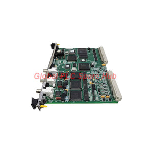

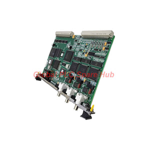
IS215VCMIH2C GE Speedtronic Mark VI VME Communication Board
Manufacturer: GE
Product No.: IS215VCMIH2C
Condition: In stock
Product Type: Communication Board
Product Origin: USA
Payment: T/T, Western Union
Weight: 500g
Shipping port: Xiamen
Warranty: 12 months
Estimate delivery times: 12-26 days (International), 3-6 days (United States).
Return within 30 days of purchase. Duties & taxes are non-refundable.
Guaranteed Safe Checkout
IS215VCMIH2C | VME Bus Master Controller Overview
The GE IS215VCMIH2C is a VME Bus Master Controller Board for the GE Mark VI Speedtronic turbine control system. It manages communication between the main controller, VME I/O boards and distributed I/O racks. It also provides an interface to the IONet control network. The VCMI board manages rack identification and associated terminal board information. It also coordinates communication across the VME backplane. In redundant Mark VI architectures, the board supports communication across R, S and T control channels. Its network interfaces help connect local and remote I/O resources. This board is particularly important in large turbine control installations. A communication fault can affect I/O availability and controller diagnostics.1. Product Identification and Hardware Profile
| Parameter | Specification |
| Manufacturer | General Electric (GE) |
| Model | IS215VCMIH2C |
| Functional Abbreviation | VCMI |
| Product Series | Mark VI Speedtronic |
| Product Type | VME Bus Master Controller Board |
| Hardware Category | VME Communication Card |
| Board Format | 6U VME |
| Processor | 32-bit |
| Memory | Dual-port memory |
| Number of Channels | 12 (source-listed specification; confirm channel definition) |
| Frame Rate | 10 ms (source-listed specification) |
| Analog Output Current | 0–20 mA (source-listed specification; verify application) |
| Power Requirement | +5 VDC |
| Operating Temperature | -30°C to +65°C |
| Network Interface | Three IONet ports |
| Serial Interface | RS-232C |
| Status Indicators | Run, Fail, Status, Reset and channel indicators |
| Manual Reference | GEH-6421M / GEH-6421 |
| Country of Origin | United States |
| Shipping Weight | Approximately 1 lb (0.45 kg) |
2. Communication Architecture and Functional Roles
The VCMI performs several communication tasks within the Mark VI control architecture. A. VME Backplane Management - Acts as the VME bus master in the control and I/O racks. - Coordinates communication between installed I/O boards. - Manages board identification within the rack. - Maintains associated terminal board identification information. - Exchanges data with the main processor modules. B. IONet Network Interface - Provides three IONet communication ports. - Supports R, S and T channel network connections. - Connects local and remote I/O resources. - Exchanges control and I/O data across the network. - Supports distributed turbine control architectures. C. Rack Communication Coordination - Supports communication between VME racks. - Coordinates I/O rack identification. - Provides an interface for remote I/O configurations. - Helps maintain communication paths across the control system. D. Processor Data Exchange - Uses dual-port memory for data exchange. - Transfers execution-related information through the control architecture. - Supports communication with main processor modules. - Works with the Mark VI application software environment.3. Front Panel Interface and Status Indicators
The front panel provides physical access to communication interfaces and diagnostic indicators.| Front Panel Element | Function |
| RS-232C Port | Serial interface for supported service and diagnostic operations. |
| IONet Port 1 | First network communication interface. |
| IONet Port 2 | Second network communication interface. |
| IONet Port 3 | Third network communication interface. |
| TX LED | Indicates network transmission activity. |
| RX LED | Indicates network reception activity. |
| CD LED | Indicates carrier detection status. |
| RUN LED | Indicates board operating status. |
| FAIL LED | Indicates a board fault condition. |
| STATUS LED | Provides additional board status information. |
| Reset Switch | Provides a hardware reset function. |
| 1, 2, 4, 8 Indicators | Provide additional diagnostic or status information. |
4. Local and Remote I/O Network Topologies
The IS215VCMIH2C supports different rack arrangements within the Mark VI control system. Topology A: Compact Local I/O Configuration - I/O boards reside in the main VME control rack. - The VCMI manages communication across the local backplane. - Three IONet ports provide the R, S and T network connections. - Additional remote I/O racks are not required in this arrangement. Topology B: Distributed I/O Configuration - The main control rack connects to remote I/O racks. - Each I/O rack uses its own VCMI board. - IONet provides the communication path between supported racks. - Distributed field signals can reach the main control architecture. - Rack identification supports organized I/O management. Topology C: TMR Control Configuration - R, S and T represent the three redundant control channels. - Corresponding I/O resources support the redundant architecture. - Communication paths must match the approved system topology. - All three channels require correct network and rack configuration.5. Installation and Configuration Guidelines
Correct installation is essential for stable VME and network communication. Mechanical Installation 1. Confirm the full part number and hardware revision. 2. Verify the board format and rack compatibility. 3. Isolate the rack power according to maintenance procedures. 4. Inspect the VME backplane connector. 5. Check the board for physical damage. 6. Insert the card into the approved rack position. 7. Secure the board using the designated retaining hardware. Network Installation 1. Identify the R, S and T network assignments. 2. Check each IONet cable and connector. 3. Verify network topology against the system drawings. 4. Confirm remote rack identification. 5. Inspect cable routing and termination. 6. Check TX, RX and CD indicator activity. 7. Review controller communication status after startup. Configuration Verification - Confirm installed I/O board identification. - Check terminal board associations. - Verify rack configuration in the application software. - Review communication status for each redundant channel. - Confirm that the remote I/O topology matches the engineering drawings. Do not change network assignments or rack configurations without an approved system change procedure.6. Field Diagnostics and Fault Isolation
The VCMI provides several useful diagnostic points. Engineers can use the front panel, network activity indicators and controller diagnostics to isolate communication problems.| Observed Condition | Potential Cause | Recommended Action |
| RUN indicator abnormal | Startup or board execution problem | Check board seating, power and controller diagnostics. |
| FAIL indicator active | Board fault or internal diagnostic failure | Record the LED state and review fault logs. |
| No TX activity | Network transmission problem | Inspect network configuration and communication status. |
| No RX activity | Missing incoming network traffic | Check the connected network path and remote device. |
| CD indicator abnormal | Carrier or physical network connection issue | Inspect cable continuity and connector condition. |
| Remote I/O unavailable | IONet cable, rack or configuration fault | Check remote VCMI status and rack identification. |
| One redundant channel unavailable | Channel-specific communication fault | Compare R, S and T network diagnostics. |
| I/O board identification mismatch | Incorrect rack configuration or terminal association | Compare installed hardware with configuration records. |
7. Compatible Equipment and Industrial Applications
The IS215VCMIH2C is designed for the GE Mark VI turbine control platform. It is suitable for installations that require VME rack coordination and distributed I/O communication. Compatible Equipment Groups - GE Mark VI VME control racks. - Compatible GE Mark VI I/O racks. - Main turbine controller assemblies. - Remote I/O rack assemblies. - Supported IONet network infrastructure. - Associated Mark VI I/O boards and terminal boards. - R, S and T redundant control channel installations. Compatibility with individual boards depends on the rack configuration, hardware revision and application software. Typical Industrial Applications - Gas turbine generator control systems. - Steam turbine control systems. - Combined-cycle power plants. - Distributed turbine I/O installations. - Industrial power generation facilities. - Turbine auxiliary control systems. - Wind turbine control applications where the installed system specifies this hardware. - Large industrial turbine automation projects.8. Global PLC Spare HUB's Insight
From a field engineering perspective, the VCMI should be treated as a communication infrastructure component rather than a simple I/O expansion card. Its condition directly affects data exchange between the controller and the installed I/O architecture. Practical Case 1: Remote I/O Rack Communication Loss An engineer may find that the main controller remains operational while a remote I/O rack becomes unavailable. In this situation, replacing the VCMI immediately is not the best first step. Inspect the IONet cable and connector first. Then check TX, RX and CD indicators at both ends of the communication path. If physical connections appear normal, review the remote rack identification and controller configuration. This helps determine whether the fault belongs to the network path or the installed hardware. Practical Case 2: One Redundant Channel Reports a Communication Fault A TMR installation may report an abnormal communication state on one channel. Compare the R, S and T channel diagnostics. Check the corresponding network cables, rack connections and VCMI status. If only one channel shows abnormal activity, focus the investigation on that channel. Avoid changing all three network configurations at the same time. Practical Case 3: I/O Board Identification Mismatch An I/O board replacement may result in an identification or configuration alarm. Check the installed board model and terminal board association. Compare the physical rack arrangement with the engineering database. The VCMI manages rack and board identification information. Incorrect configuration records can therefore affect I/O recognition. Our Engineering Recommendation For critical Mark VI installations, maintain a verified VCMI spare with the correct hardware revision. Before replacement, record the existing network assignments and rack configuration. Confirm the replacement board against the applicable GE manual and system configuration.9. Why Choose IS215VCMIH2C?
- VME Bus Master Control: Coordinates communication across the control rack. - IONet Connectivity: Provides three network interfaces for system communication. - Distributed I/O Support: Connects compatible local and remote I/O resources. - TMR Architecture: Supports communication arrangements using R, S and T channels. - Dual-Port Memory: Supports data exchange within the controller architecture. - Front Panel Diagnostics: Provides LEDs and a reset switch for maintenance. - Industrial Design: Supports the specified Mark VI operating environment.10. Packaging, Warranty and International Shipping
Product Supply - Manufacturer: General Electric. - Part Number: IS215VCMIH2C. - Product Type: VME Bus Master Controller Board. - Product Series: Mark VI. - Country of Origin: United States. Standard Packaging - 1 × GE IS215VCMIH2C Controller Board. - Protective packaging for electronic components. - Shipping documentation. - Product identification information. Warranty - 12-month warranty from the agreed warranty start date. - Order and product identification records. - Technical assistance for model verification. - Warranty service according to the agreed sales terms. Shipping Methods - FedEx International Express. - UPS Worldwide. - DHL Express. Dispatch Time Orders are arranged for shipment within 24–48 hours after order confirmation and stock verification. International shipping and tracking support are available.11. Frequently Asked Questions
Q1: What information should engineers record before replacing a VCMI board? Record the complete model number, hardware revision, rack position and network assignments. Photograph the existing cable connections and LED states. Also preserve the current I/O rack configuration. These records help prevent incorrect connections during replacement. Q2: Why can a controller operate normally while some I/O data becomes unavailable? The main processor and I/O communication paths perform different functions. A local controller may remain operational while an IONet connection or remote rack fails. Engineers should inspect the affected communication path before investigating the entire controller. Q3: What is the engineering significance of dual-port memory? Dual-port memory provides a shared data exchange mechanism between processing or communication resources. It supports efficient information transfer within the controller architecture. Its operation should be evaluated through the applicable GE diagnostics rather than external memory testing. Q4: Can the IS215VCMIH2C be installed in any 6U VME rack? No. A matching physical format does not guarantee electrical or functional compatibility. Confirm the rack backplane, slot assignment, power requirements and Mark VI hardware configuration before installation. Q5: How should buyers evaluate the C revision when sourcing a replacement? Compare the complete ordering number and revision with the installed board. Check the system manual and approved hardware list for revision compatibility. Do not assume that an earlier VCMI revision provides identical functionality. Request confirmation before substituting a different suffix.Request a Quote | IS215VCMIH2C
Global PLC Spare HUB supplies industrial control components for turbine automation, power generation and distributed control systems. Contact our sales team for: - IS215VCMIH2C pricing and availability. - Hardware revision verification. - Mark VI rack compatibility checks. - VME and IONet application information. - International shipping arrangements. Need a GE Mark VI VME Bus Master Controller Board? Contact Global PLC Spare HUB today for a quotation and delivery information.Tags
Q: Are these parts 100% original and new?
A: Yes. Every component is guaranteed to be 100% original, brand-new, and factory-sealed. We also provide a 12-month comprehensive warranty for your peace of mind.
Q: How fast is the shipping to my country?
A: For in-stock items, we offer same-day dispatch. International express shipping (DHL/FedEx/UPS) typically delivers within 3–5 business days worldwide.
Q: Can I get a formal quotation with shipping costs?
A: Absolutely. Our sales team is ready to provide a detailed Proforma Invoice (PI) including the most competitive shipping rates for your location.
Q: Do you offer discounts for bulk orders?
A: We provide volume-based pricing for large projects or multiple-item orders. Please contact us to get our Best Price Guarantee.
12-Month Comprehensive Warranty
Every part supplied by Global PLC Spare Hub is covered by a 12-month warranty from the date of invoice.
- Coverage: Functional defects and hardware failures under normal operating conditions.
- Commitment: We provide immediate repair, replacement, or a full refund for any verified defective components to minimize your operational downtime.
Returns & Exchange Policy
We offer a 30-day return policy to ensure you receive the exact part your system requires.
- Eligibility: Returns are accepted for uninstalled items in their original, factory-sealed packaging.
- RMA Process: Please contact our support team to obtain a Return Merchandise Authorization (RMA) number before shipping.
- Fast Processing: Refunds or exchanges are processed within 3–5 business days after the returned item passes our technical inspection.
Need Technical Assistance?Not sure if this part is compatible with your system? [Consult our Engineers] before purchasing to ensure 100% compatibility.
People Also Bought


