


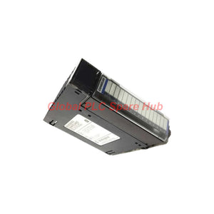
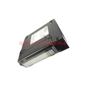
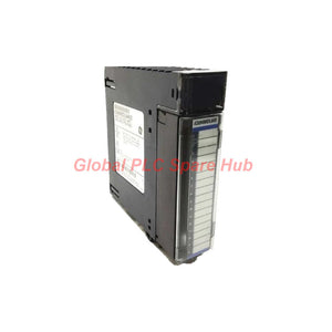
IC694MDL645 PACSystems RX3i 24VDC Digital Input
Manufacturer: GE Fanuc
Product No.: IC694MDL645
Condition: In stock
Product Type: Digital Input Module
Product Origin: USA
Payment: T/T, Western Union
Weight: 450g
Shipping port: Xiamen
Warranty: 12 months
Estimate delivery times: 12-26 days (International), 3-6 days (United States).
Return within 30 days of purchase. Duties & taxes are non-refundable.
Guaranteed Safe Checkout
IC694MDL645 | PACSystems RX3i 16-Point DC Digital Input Module
The GE Fanuc IC694MDL645 is a 16-point discrete input module for monitoring 24 VDC field signals in industrial control systems. It supports positive or negative logic wiring and groups all 16 input points around a shared common terminal.
For commissioning engineers, the key selection factors are the field signal voltage, input switching thresholds, common-terminal wiring, and controller architecture. Sixteen green channel LEDs help technicians compare the physical input state with the controller's observed status during troubleshooting.
01 | Signal Architecture and Input Characteristics
| Manufacturer | GE Fanuc / GE Intelligent Platforms |
| Current brand association | Emerson Automation |
| Model | IC694MDL645 |
| Product family | PACSystems RX3i |
| Module type | Discrete DC input module |
| Number of inputs | 16 points |
| Input grouping | One group with a shared common terminal |
| Nominal input voltage | 24 VDC |
| Permitted input signal range | 0–30 VDC, according to supplied specifications |
| Wiring logic | Positive or negative logic; confirm the applicable wiring diagram |
| On-state voltage | 11.5–30 VDC |
| Off-state voltage | 0–5 VDC |
| Input current | 7 mA at rated conditions, as supplied |
| Minimum on-state current | 3.2 mA, as supplied |
| Maximum off-state current | 1.1 mA, as supplied |
| Typical on-state response | 7 ms, as supplied |
| Backplane current at 5 VDC | 80 mA |
| 24 VDC supply current | 125 mA, as supplied; confirm the applicable supply configuration |
| Isolation | Source data states 250 VAC continuous and 1500 VAC for one minute; verify the isolation boundary in the official manual |
| Operating temperature | 0 to 60°C (32 to 140°F) |
| Storage temperature | -40 to 85°C (-40 to 185°F) |
| Relative humidity | 5%–95%, non-condensing |
| Channel indicators | 16 green input-status LEDs |
02 | How Engineers Use the Input Signals
Field signal acquisition: The module monitors discrete states from field devices and makes those states available to the control application. Typical signals include equipment run feedback, limit-switch positions, pushbutton commands, and auxiliary contact status.
Logic compatibility: Positive or negative logic wiring supports different field circuit arrangements. Engineers must check the actual sourcing or sinking arrangement, common-terminal polarity, and field supply connections before energizing the circuit.
Channel-level visibility: Each input has a corresponding green LED. This indication helps technicians identify whether the module detects a field signal during startup, maintenance, or fault isolation.
Response-time considerations: The supplied data lists a typical on-state response of 7 ms. For high-speed counting, pulse capture, or tightly timed interlocks, verify the complete input timing specifications and application requirements before selecting this module.
03 | Typical Equipment and Application Scenarios
- Machine control panels: Read pushbuttons, selector switches, travel limits, and machine-position contacts.
- Motor control systems: Monitor contactor auxiliary contacts, run feedback, and local permissive signals.
- Material handling equipment: Acquire conveyor limit switches, gate-position signals, and transfer-station status.
- Process skids: Monitor discrete equipment states and dry-contact feedback within an RX3i-based control architecture.
- Plant equipment upgrades: Replace a failed input module when the existing rack, controller configuration, wiring, and hardware revision support the replacement.
These are typical application examples, not a guarantee of suitability for every machine. Safety-related functions, high-speed signal acquisition, and applications with special electrical requirements need separate engineering validation.
04 | Installation and Commissioning Checks
- Verify the rack and controller: Confirm the module position, rack configuration, controller family, and firmware or hardware requirements using the applicable system manual.
- Isolate the power supply: Follow the plant's lockout and electrical safety procedures before removing or installing the module.
- Check the common terminal: Identify the shared common connection and confirm that all field circuits use the intended reference and polarity.
- Measure field voltage: Check the signal at the module terminals. Confirm that the ON voltage reaches the specified threshold and the OFF voltage falls within the defined OFF-state range.
- Test each channel: Operate field switches individually and compare the physical state, channel LED, and controller input value.
- Confirm the power budget: Include the module's backplane load and any field-device supply demand in the system power calculation.
- Record the baseline: Document channel assignments, terminal wiring, normal LED states, and controller diagnostics for future maintenance.
05 | Global PLC Spare HUB's Insight
In field troubleshooting, a discrete input fault can originate from the sensor, wiring, common reference, supply voltage, terminal connection, or module itself. Replacing the module before checking these conditions may leave the original fault unresolved.
- LED remains OFF: Measure the signal directly at the input terminal. Check the field supply, contact state, wiring continuity, and common-terminal connection.
- LED remains ON unexpectedly: Check for leakage current, cross-wiring, an incorrect common reference, or a field device that has not fully opened.
- LED changes but the PLC value does not: Review the controller's I/O configuration, channel addressing, module recognition, and application logic.
- Several channels fail together: Inspect the shared common, field supply, connector seating, and group wiring before suspecting simultaneous channel failures.
- Intermittent input transitions: Record the voltage during the fault and inspect loose terminals, electrical noise, unstable supply conditions, and contact bounce.
Engineering note: The supplied specifications contain both a 7 mA input-current figure and separate ON/OFF current thresholds. Confirm their exact definitions in the official IC694MDL645 manual before calculating leakage margins or designing interface circuits. The stated isolation values also require confirmation of their applicable isolation boundary.
06 | System Compatibility and Replacement Planning
The IC694MDL645 belongs to the PACSystems RX3i product family. The supplied description identifies local and distributed I/O use in RX3i systems and distributed I/O use in RX7i systems. Confirm these arrangements against the relevant controller, rack, interface, firmware, and hardware documentation before ordering.
- Match the complete model number and verify the existing module's hardware revision.
- Confirm the control platform and intended local or remote I/O arrangement.
- Check terminal wiring, common polarity, input thresholds, and field-device current requirements.
- Review the controller configuration and I/O addressing before commissioning a replacement.
- Do not assume that similar-looking modules share the same electrical characteristics or configuration requirements.
07 | Supply, Warranty and Logistics
- Product condition: New and original, subject to order confirmation and available stock.
- Warranty: 12 months, subject to the seller's written warranty terms.
- Dispatch: Target dispatch within 24–48 hours after order and stock confirmation, subject to processing requirements.
- Shipping options: FedEx, UPS, or DHL, subject to destination and service availability.
- Before ordering: Provide the full model number, required quantity, delivery country, and existing system details for a compatibility and quotation check.
08 | Frequently Asked Questions
Q1. How can I distinguish a field wiring fault from an internal input-module fault?
Measure the voltage at the module terminal while changing the field device state. If the voltage does not reach the required threshold, investigate the sensor, supply, wiring, and common connection first. If the voltage meets the specified conditions but the LED does not respond, check the terminal connection and module documentation before considering replacement.
Q2. Can a two-wire proximity sensor drive an input directly?
Do not assume direct compatibility from the nominal 24 VDC rating alone. Check the sensor's residual OFF-state current, voltage drop, output polarity, and the module's switching thresholds. If leakage current prevents a clean OFF state, an approved interface device may be necessary.
Q3. What information should I provide when requesting a replacement quotation?
Provide IC694MDL645, the quantity, clear photographs of the existing label and terminals, the controller or rack model, and the destination country. These details help the supplier check stock, identify potential configuration constraints, and quote suitable shipping options.
Q4. What should I investigate if several input channels report incorrect states at the same time?
Start with shared circuit elements rather than replacing individual sensors. Check the common terminal, 24 VDC supply, wiring harness, terminal seating, and grounding arrangement. Compare channel LEDs with controller input values to narrow the fault to the field circuit, module interface, or controller configuration.
Q5. Is IC694MDL645 a suitable choice for fast pulse or safety-critical signals?
Do not select it solely because it accepts 24 VDC signals. The supplied on-state response is 7 ms, so verify the complete response-time specification against the required pulse width and event timing. For safety-related applications, confirm the required safety architecture and approved hardware; this standard discrete input module should not be treated as a safety-rated device without explicit documentation.
Tags
Q: Are these parts 100% original and new?
A: Yes. Every component is guaranteed to be 100% original, brand-new, and factory-sealed. We also provide a 12-month comprehensive warranty for your peace of mind.
Q: How fast is the shipping to my country?
A: For in-stock items, we offer same-day dispatch. International express shipping (DHL/FedEx/UPS) typically delivers within 3–5 business days worldwide.
Q: Can I get a formal quotation with shipping costs?
A: Absolutely. Our sales team is ready to provide a detailed Proforma Invoice (PI) including the most competitive shipping rates for your location.
Q: Do you offer discounts for bulk orders?
A: We provide volume-based pricing for large projects or multiple-item orders. Please contact us to get our Best Price Guarantee.
12-Month Comprehensive Warranty
Every part supplied by Global PLC Spare Hub is covered by a 12-month warranty from the date of invoice.
- Coverage: Functional defects and hardware failures under normal operating conditions.
- Commitment: We provide immediate repair, replacement, or a full refund for any verified defective components to minimize your operational downtime.
Returns & Exchange Policy
We offer a 30-day return policy to ensure you receive the exact part your system requires.
- Eligibility: Returns are accepted for uninstalled items in their original, factory-sealed packaging.
- RMA Process: Please contact our support team to obtain a Return Merchandise Authorization (RMA) number before shipping.
- Fast Processing: Refunds or exchanges are processed within 3–5 business days after the returned item passes our technical inspection.
Need Technical Assistance?Not sure if this part is compatible with your system? [Consult our Engineers] before purchasing to ensure 100% compatibility.
People Also Bought


