


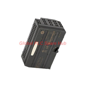

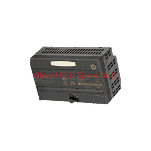
IC200ALG260 Emerson VersaMax 8-Channel Analog Input
Manufacturer: GE Fanuc
Product No.: IC200ALG260
Condition: In stock
Product Type: Analog Input Module
Product Origin: USA
Payment: T/T, Western Union
Weight: 200g
Shipping port: Xiamen
Warranty: 12 months
Estimate delivery times: 12-26 days (International), 3-6 days (United States).
Return within 30 days of purchase. Duties & taxes are non-refundable.
Guaranteed Safe Checkout
IC200ALG260 Analog Input Module – Signal Acquisition for VersaMax PLC Systems
The GE Fanuc IC200ALG260 provides an eight-channel analog interface for the VersaMax PLC platform. It receives industrial voltage or current signals and converts them into digital values for PLC processing.
The module supports 4–20 mA current signals, 0–10 VDC unipolar signals, and −10 to +10 VDC bipolar signals. Engineers can select the required input mode and measurement range through module configuration.
All eight inputs use a single-ended arrangement. Each measurement references the field ground rather than a dedicated differential input pair. This design suits conventional process instrumentation, but it requires careful grounding and noise management.
01 | Signal Interface and Measurement Architecture
| Interface feature | Engineering description |
|---|---|
| Input channels | 8 single-ended analog inputs |
| Signal modes | Voltage or current |
| Current range | 4–20 mA |
| Unipolar voltage | 0–10 VDC |
| Bipolar voltage | −10 to +10 VDC |
| Conversion resolution | 12 bits |
| Input configuration | Range select and mode select |
| Input topology | Single-ended, common reference |
The module converts field signals into digital values for the controller. Its 12-bit resolution provides the measurement granularity required by many standard process applications.
Important configuration point: Select the correct signal mode and range before connecting field instruments. Confirm whether the application uses voltage or current signals. Do not assume that different channels can use different signal modes without checking the applicable hardware manual.
02 | Conversion Performance and Electrical Characteristics
| Parameter | Specification |
|---|---|
| Typical accuracy at 25°C | ±0.3% of full scale |
| Maximum accuracy at 25°C | ±0.5% of full scale |
| Maximum accuracy, 0–60°C | ±1% of full scale |
| Voltage input impedance | 126 kΩ maximum |
| Current input impedance | 200 Ω maximum |
| Filter response time | 5 ms in voltage and current modes |
| Update rate | 0.4 ms, as specified in the supplied data |
| Channel-to-channel crosstalk rejection | 30 dB minimum |
Accuracy depends on operating temperature and the selected input range. Engineers should use the full-scale accuracy figures when estimating measurement uncertainty.
The specified 5 ms filter response and 0.4 ms update rate describe different performance characteristics. Do not treat the update rate as the complete analog signal settling time.
03 | Backplane Power, Isolation and Status Monitoring
- Backplane supply: The module receives operating power through the VersaMax backplane.
- Current consumption: The supplied specifications list 125 mA and 130 mA at 5 VDC. Confirm the applicable hardware revision documentation before final power-budget calculations.
- External power: The module does not normally require a separate external supply for its internal operation. Connected field transceivers may require their own power source.
- Optical isolation: 250 VAC continuous and 1500 VAC for one minute, according to the supplied data.
- Thermal derating: No thermal derating feature is specified in the supplied product information.
The front panel provides two green status indicators:
- OK LED: Indicates that the module has backplane power and is operating normally.
- INT PWR LED: Indicates the availability of internal field-side power for the analog circuits.
The module also supports a loss-of-internal-power diagnostic. This helps maintenance personnel distinguish a field-side power problem from a controller communication or configuration issue.
04 | Installation and Commissioning: Practical Engineering Checks
Single-ended analog wiring requires particular attention to grounding and cable routing. The following checks help reduce commissioning problems.
- Verify the signal type. Check each instrument output against the selected voltage or current operating mode.
- Confirm the measurement range. Match the configured range to the transmitter output and expected process values.
- Review the common reference. Ensure field signal returns use the correct reference connection. Avoid unintended ground loops between instruments and control cabinets.
- Separate analog wiring. Route signal cables away from motor feeders, variable-frequency drives, contactors, and other high-noise conductors.
- Check field power. Verify transmitter supply voltage and polarity before evaluating the module input.
- Compare readings. Use a calibrated signal source to compare the applied input with the PLC engineering value.
Because the inputs are single-ended, this module offers less inherent rejection of electromagnetic interference than a differential input arrangement. Shielding, grounding, cable separation, and suitable signal conditioning become important in electrically noisy installations.
05 | Fault Isolation and Maintenance Guidance
| Observed condition | Recommended engineering checks |
|---|---|
| OK LED is off | Inspect backplane seating, rack power, and module installation. |
| INT PWR LED is off | Check internal field-side power availability and connected field circuits. |
| Reading remains at zero | Verify transmitter power, loop continuity, signal polarity, and configured input mode. |
| Reading fluctuates unexpectedly | Inspect grounding, shielding, cable routing, and nearby electrical noise sources. |
| PLC value differs from the reference instrument | Check range selection, scaling, calibration, and signal-source accuracy. |
For module error handling, the supplied information identifies two possible reactions: hold the last state or use a predefined value. Confirm the actual configured behavior before relying on either response in a process safety or control strategy.
06 | Application Suitability and Selection Considerations
The IC200ALG260 suits VersaMax installations that require multiple standard analog measurement points. Typical applications include pressure transmitters, flow measurement, level monitoring, and other process instruments with compatible voltage or current outputs.
Before selecting this module, evaluate the following:
- Confirm that the required signal range matches the supported input modes.
- Check whether the single-ended topology suits the field grounding arrangement.
- Evaluate the specified accuracy against the process measurement requirements.
- Include module current consumption in the rack power budget.
- Check controller, rack, configuration software, and firmware compatibility.
For applications with long cable runs or substantial electrical interference, consider whether additional signal isolation or conditioning is necessary.
07 | Frequently Asked Questions
Q1: What should engineers check when the PLC value changes after replacing a transmitter?
First, compare the replacement instrument's output type and range with the existing configuration. A transmitter configured for 0–10 V cannot directly replace a 4–20 mA device without changing the interface arrangement. Also verify scaling in the PLC program. A correct electrical signal can still produce an incorrect process value when the engineering range remains unchanged.
Q2: How can maintenance teams distinguish a wiring problem from an input configuration problem?
Apply a known signal using a calibrated loop or voltage source. Measure the signal at the module terminals and compare it with the PLC reading. If the terminal signal is incorrect, investigate the instrument, wiring, and field supply. If the terminal signal is correct but the digital value is wrong, review the selected range, operating mode, and controller scaling.
Q3: What precautions should be taken when several transmitters share a cabinet ground?
Review the grounding arrangement before connecting all signal returns. Different instrument ground potentials can introduce unwanted offsets into single-ended measurements. Use a consistent grounding strategy, maintain suitable cable shielding, and avoid creating multiple unintended return paths. Where ground potential differences remain significant, evaluate external signal isolation.
Q4: Why might a stable signal source still produce fluctuating readings in an operating plant?
A stable source does not eliminate interference introduced by field wiring. Long parallel cable runs, switching loads, poor shield termination, and grounding differences can affect single-ended measurements. Test the input with a local calibrated source. If the reading stabilizes, inspect the field cable route and grounding before replacing the module.
Q5: What information should technicians record before removing this module during maintenance?
Record the existing range and mode settings, PLC channel assignments, field terminal wiring, and current process readings. Also document the LED status and any active diagnostics. These records help technicians restore the original configuration and identify wiring changes after replacement. Follow the site's isolation and rack maintenance procedures before removing hardware.
08 | Product Identification and Supply Information
- Manufacturer: GE Fanuc (formerly); Emerson Automation (current ownership context)
- Series: VersaMax
- Model: IC200ALG260
- Product type: Analog Input Module
- Input configuration: 8-channel, single-ended
Package contents: IC200ALG260 analog input module. Additional accessories or documentation should be confirmed when ordering.
Contact our team to confirm model identification, technical compatibility, and current availability. We provide a 12-month warranty and support shipping arrangements through DHL, FedEx, and UPS. Typical dispatch is 24–48 hours, subject to stock confirmation.
Request a quotation for the GE Fanuc IC200ALG260 and provide your application details for a more accurate technical review.

Tags
Q: Are these parts 100% original and new?
A: Yes. Every component is guaranteed to be 100% original, brand-new, and factory-sealed. We also provide a 12-month comprehensive warranty for your peace of mind.
Q: How fast is the shipping to my country?
A: For in-stock items, we offer same-day dispatch. International express shipping (DHL/FedEx/UPS) typically delivers within 3–5 business days worldwide.
Q: Can I get a formal quotation with shipping costs?
A: Absolutely. Our sales team is ready to provide a detailed Proforma Invoice (PI) including the most competitive shipping rates for your location.
Q: Do you offer discounts for bulk orders?
A: We provide volume-based pricing for large projects or multiple-item orders. Please contact us to get our Best Price Guarantee.
12-Month Comprehensive Warranty
Every part supplied by Global PLC Spare Hub is covered by a 12-month warranty from the date of invoice.
- Coverage: Functional defects and hardware failures under normal operating conditions.
- Commitment: We provide immediate repair, replacement, or a full refund for any verified defective components to minimize your operational downtime.
Returns & Exchange Policy
We offer a 30-day return policy to ensure you receive the exact part your system requires.
- Eligibility: Returns are accepted for uninstalled items in their original, factory-sealed packaging.
- RMA Process: Please contact our support team to obtain a Return Merchandise Authorization (RMA) number before shipping.
- Fast Processing: Refunds or exchanges are processed within 3–5 business days after the returned item passes our technical inspection.
Need Technical Assistance?Not sure if this part is compatible with your system? [Consult our Engineers] before purchasing to ensure 100% compatibility.
People Also Bought


