


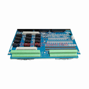
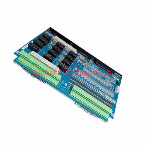

GE IS400TDBTH6A 125V DC Contact Input Terminal Board
Manufacturer: GE
Product No.: IS400TDBTH6A
Condition: In stock
Product Type: Input Terminal Board
Product Origin: USA
Payment: T/T, Western Union
Weight: 500g
Shipping port: Xiamen
Warranty: 12 months
Estimate delivery times: 12-26 days (International), 3-6 days (United States).
Return within 30 days of purchase. Duties & taxes are non-refundable.
Guaranteed Safe Checkout
Product Overview
The GE IS400TDBTH6A is a discrete input/output terminal board for the GE Mark VIe control system. It provides a centralized interface for field contact signals and relay output circuits.
This terminal board supports 24 group-isolated contact inputs with a nominal 125 V DC wetting voltage. Its H6A configuration accepts an operating voltage range of 100–145 V DC.
The TDBT architecture supports Triple Modular Redundancy (TMR) through three dedicated PDIO I/O Pack connections. Each input signal reaches the associated redundant processing channels.
The board also provides 12 Form-C relay outputs for discrete control applications. Pluggable terminal blocks simplify field wiring and replacement procedures.
Engineers commonly apply this architecture to turbine protection, equipment sequencing, auxiliary systems, and industrial process control.
Technical Specifications
| Manufacturer | General Electric (GE) |
| Product Model | IS400TDBTH6A |
| Related Ordering References | IS400TDBTH6AEY / IS400TDBTH6AEF |
| Product Series | Mark VIe / Speedtronic |
| Product Type | Discrete I/O Terminal Board |
| Board Architecture | TDBT – Triple Modular Redundant |
| Contact Inputs | 24 channels, group-isolated |
| Input Signal Type | Dry contact with external wetting voltage |
| Nominal Wetting Voltage | 125 V DC |
| Wetting Voltage Range | 100–145 V DC |
| Input Current | 2.55 mA for channels 1–21; 10 mA for channels 22–24 |
| Hardware Input Filter | 4 ms |
| Relay Outputs | 12 Form-C relay circuits |
| Relay Contacts | Normally Open, Common, Normally Closed |
| Output Circuit Rating | 5 A design current rating; verify individual relay contact limits |
| Redundancy Interfaces | 3 PDIO I/O Pack connectors |
| Communication Interface | PDIO I/O Pack to Mark VIe IONet |
| Terminal Connection | Euro-style pluggable terminal blocks |
| Mounting Method | DIN-Rail or cabinet flat mounting |
| Installation Wiring | TB1 relay circuits; TB2 contact inputs |
| Reference Manual | GEH-6721, Mark VIe Control Systems Guide |
Input Signal Processing and Electrical Performance
The IS400TDBTH6A uses dedicated signal-conditioning circuits for field contact inputs.
- Input threshold: Approximately 50% of the applied wetting voltage.
- Hardware filtering: A fixed 4 ms filter suppresses rapid signal disturbances.
- Noise suppression: Input circuits reduce high-frequency interference and transient surges.
- Signal isolation: The PDIO acquisition circuitry uses optical isolation between field signals and control logic.
- Input current: Channels 1–21 draw approximately 2.55 mA at nominal 125 V DC.
- Remaining channels: Channels 22–24 draw approximately 10 mA.
This product handles discrete contact states rather than analog measurements. Frequency response, sensor sensitivity, linearity, and measurement resolution do not apply.
Its 4 ms hardware filter defines the input conditioning interval. It does not represent the complete system response time.
TMR Redundancy and System Architecture
The TDBT H6A supports a three-channel redundant architecture within GE Mark VIe systems.
- Three PDIO interfaces: The terminal board accommodates three dedicated I/O Packs.
- Shared field inputs: Each contact input connects to the redundant acquisition paths.
- Controller integration: The three I/O paths connect with their corresponding control channels.
- Redundant processing: The Mark VIe architecture manages channel status and control data.
- Fault tolerance: System-level redundancy helps maintain control availability during individual channel failures.
Engineering note: TMR operation requires the complete three-channel configuration. The terminal board alone cannot provide autonomous redundancy or automatic failover.
Typical Industrial Applications
| Gas Turbine Control | Acquires contact signals from limit switches, auxiliary equipment, and operating interlocks. |
| Steam Turbine Systems | Interfaces equipment status signals and relay-based control circuits. |
| Power Generation | Supports redundant discrete signal acquisition in turbine control cabinets. |
| Compressor Stations | Monitors valve positions, equipment permissives, and auxiliary operating states. |
| Oil and Gas Facilities | Connects field contact signals to centralized turbine control systems. |
| Industrial Process Control | Handles equipment sequencing and discrete interlock interfaces. |
Installation Guidelines
Correct installation protects signal integrity and maintains the intended TMR architecture.
- Verify the model: Check the board nameplate and confirm the H6A configuration.
- Isolate power: Follow site lockout and electrical safety procedures before installation.
- Prepare mounting: Install the board assembly on its DIN-Rail carrier or cabinet mounting structure.
- Connect field inputs: Use TB2 for the 24 contact input circuits.
- Connect relay outputs: Use TB1 for the 12 relay circuits.
- Connect wetting voltage: Apply the correct floating 125 V DC supply through the JE1 connector.
- Install PDIO Packs: Connect the three I/O Packs to their designated D-type connectors.
- Check grounding: Terminate cable shields on a separate grounding bracket.
- Inspect wiring: Verify terminal assignments, polarity, insulation, and connector seating.
- Complete commissioning: Confirm channel status and controller communication before operational release.
Important: The H6A wetting voltage outputs share a parallel supply connection. Verify the GE wiring diagram before connecting field circuits.
Commissioning and Maintenance
Commissioning should verify the electrical interface and the complete redundant control path.
- Voltage verification: Measure the wetting supply and confirm its 100–145 V DC operating range.
- Contact testing: Operate each field contact and verify the corresponding controller indication.
- Filter verification: Check the 4 ms hardware filtering against the application requirements.
- Relay testing: Verify NO, NC, and COM contact operation under approved test conditions.
- TMR verification: Confirm all three PDIO channels report the expected operating status.
- Alarm inspection: Review controller diagnostics and I/O Pack fault messages.
- Wiring inspection: Check loose terminals, damaged insulation, and corrosion during scheduled maintenance.
For field replacement, record terminal assignments before removing existing connections. Compare the replacement board revision and connector configuration before energizing the system.
Diagnostic Capabilities and Troubleshooting
The Mark VIe system provides diagnostic information through the PDIO acquisition and controller architecture.
| Diagnostic Condition | Recommended Engineering Check |
| Loss of wetting voltage | Check the 125 V DC supply, JE1 connector, and field wiring. |
| Input does not respond during testing | Inspect the contact, terminal connections, and input signal path. |
| Incorrect input indication | Verify the contact state, voltage threshold, and channel configuration. |
| PDIO communication fault | Inspect the IONet connection, I/O Pack seating, and controller diagnostics. |
| Redundant channel disagreement | Compare the three channel states and investigate the affected field circuit. |
| Relay output malfunction | Check external power, relay contacts, wiring, and connected loads. |
Practical example: A turbine auxiliary contact remains inactive during a commissioning test.
First, measure the wetting voltage at the terminal board. Next, inspect the field contact and TB2 wiring.
Then, compare the corresponding PDIO indications across all three channels. This sequence helps distinguish field wiring faults from acquisition-path faults.
Compatibility and Replacement Considerations
- Control platform: Designed for compatible GE Mark VIe TMR discrete I/O configurations.
- I/O Pack: Requires three compatible PDIO I/O Packs for the intended TMR arrangement.
- Voltage configuration: The H6A version supports nominal 125 V DC wetting voltage.
- Terminal arrangement: Confirm TB1, TB2, JE1, and PDIO connector assignments.
- Firmware compatibility: Verify I/O Pack revisions and ControlST configuration requirements.
- Replacement verification: Compare the original board number, hardware revision, and complete ordering suffix.
Do not substitute an H2A or H4A board without reviewing the system voltage requirements. Their wetting voltage configurations differ from H6A.
The IS400 ordering references require nameplate verification. Confirm the exact IS400TDBTH6AEY or IS400TDBTH6AEF suffix before ordering.
Environmental Conditions and Certifications
- Operating temperature: Confirm the applicable rating from the exact IS400 hardware revision documentation.
- Environmental resistance: Follow the approved cabinet enclosure and installation requirements.
- EMI protection: The input circuits provide noise suppression and transient protection.
- Electrical isolation: The PDIO acquisition path provides optical isolation.
- Certifications: Confirm applicable approvals through the product nameplate and manufacturer documentation.
This product description does not assign an unsupported SIL, ATEX, IECEx, or hazardous-location certification. Verify project-specific approval requirements before installation.
Global PLC Spare HUB's Insight
In turbine control applications, terminal board selection must match the field voltage and redundancy architecture.
The IS400TDBTH6A is particularly relevant when a project requires 125 V DC contact acquisition within a TMR control arrangement.
Consider a turbine auxiliary system with three redundant PDIO acquisition channels. A single field contact connects through TB2 to the three processing paths.
If the controller reports a channel disagreement, engineers should first inspect the field contact and shared wiring. They should then compare the individual PDIO channel diagnostics.
This approach helps identify whether the problem originates in the field circuit, terminal interface, or acquisition channel.
Our engineering recommendation: Always verify the complete terminal board part number, H6A voltage rating, and PDIO compatibility before replacement.
Do not select this board solely by its physical appearance. Electrical configuration and TMR connector compatibility determine successful integration.
Packaging, Shipping and Warranty
- Product: GE IS400TDBTH6A discrete I/O terminal board.
- Packaging: Protective industrial packaging for transportation.
- Accessories: Included accessories depend on the confirmed order configuration.
- Warranty: 12-month warranty from the agreed delivery or warranty commencement date.
- Shipping: FedEx, UPS, and DHL international delivery options.
- Dispatch: Typically within 24–48 hours after order and stock confirmation.
- Technical Support: Assistance with model verification and compatibility inquiries.
Please confirm the terminal board revision and included accessories before placing your order.
Frequently Asked Questions (FAQ)
Q1: What is the primary function of the GE IS400TDBTH6A?
The board interfaces 24 contact inputs and 12 relay output circuits with the GE Mark VIe control system.
Q2: Can the IS400TDBTH6A operate with 24 V DC input signals?
No, the H6A configuration uses nominal 125 V DC wetting voltage. Select the correct H2A or H4A configuration for other voltage requirements.
Q3: Does this terminal board support TMR redundancy?
Yes. The TDBT architecture supports three PDIO I/O Packs and three redundant processing paths.
Q4: Can the board operate with only one PDIO I/O Pack?
The TDBT architecture is designed for TMR operation. It is not designed for correct operation with only one PDIO Pack.
Q5: What does the 4 ms input filter mean?
It represents the hardware input filtering interval. It helps suppress rapid disturbances before the acquisition processor evaluates the contact state.
Q6: What should engineers check when an input channel fails?
Start with wetting voltage and field contact continuity. Then inspect TB2 wiring and compare PDIO diagnostic information.
Q7: Can the IS400TDBTH6A directly replace another TDBT board?
Not automatically. Verify wetting voltage, hardware revision, connector assignments, and controller configuration before replacement.
Q8: How should buyers distinguish IS400TDBTH6AEY from IS400TDBTH6AEF?
Compare the complete nameplate part number and manufacturer ordering documentation. Do not assume different suffixes have identical hardware configurations.
Q9: What information should buyers provide before ordering?
Provide the existing board number, complete suffix, system type, and required quantity. A nameplate photograph also helps verify compatibility.
Q10: Is the IS400TDBTH6A suitable for a 125 V DC turbine control project?
It is a relevant candidate for compatible TMR contact input applications. Confirm the PDIO configuration and relay requirements against the project drawings.
Request a Quote
Looking for the GE IS400TDBTH6A Mark VIe discrete I/O terminal board?
Contact Global PLC Spare HUB with your required quantity and complete part number. Our team can assist with model identification, technical verification, and delivery arrangements.
Contact us today for pricing, availability, and a competitive quotation.
Tags
Q: Are these parts 100% original and new?
A: Yes. Every component is guaranteed to be 100% original, brand-new, and factory-sealed. We also provide a 12-month comprehensive warranty for your peace of mind.
Q: How fast is the shipping to my country?
A: For in-stock items, we offer same-day dispatch. International express shipping (DHL/FedEx/UPS) typically delivers within 3–5 business days worldwide.
Q: Can I get a formal quotation with shipping costs?
A: Absolutely. Our sales team is ready to provide a detailed Proforma Invoice (PI) including the most competitive shipping rates for your location.
Q: Do you offer discounts for bulk orders?
A: We provide volume-based pricing for large projects or multiple-item orders. Please contact us to get our Best Price Guarantee.
12-Month Comprehensive Warranty
Every part supplied by Global PLC Spare Hub is covered by a 12-month warranty from the date of invoice.
- Coverage: Functional defects and hardware failures under normal operating conditions.
- Commitment: We provide immediate repair, replacement, or a full refund for any verified defective components to minimize your operational downtime.
Returns & Exchange Policy
We offer a 30-day return policy to ensure you receive the exact part your system requires.
- Eligibility: Returns are accepted for uninstalled items in their original, factory-sealed packaging.
- RMA Process: Please contact our support team to obtain a Return Merchandise Authorization (RMA) number before shipping.
- Fast Processing: Refunds or exchanges are processed within 3–5 business days after the returned item passes our technical inspection.
Need Technical Assistance?Not sure if this part is compatible with your system? [Consult our Engineers] before purchasing to ensure 100% compatibility.
People Also Bought


