


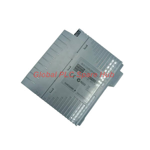
EC401-50 Yokogawa ESB Bus Coupler Module | N-IO/FIO Connectivity
Manufacturer: Yokogawa
Product No.: EC401-50
Condition: In stock
Product Type: ESB Bus Coupler Module
Product Origin: SG
Payment: T/T, Western Union
Weight: 350g
Shipping port: Xiamen
Warranty: 12 months
Estimate delivery times: 12-26 days (International), 3-6 days (United States).
Return within 30 days of purchase. Duties & taxes are non-refundable.
Guaranteed Safe Checkout
EC401-50 | Yokogawa ESB Bus Coupler Module
The Yokogawa EC401-50 is an ESB Bus Coupler Module designed to provide an ESB bus interface for N-IO/FIO systems. It supports high-speed I/O data transmission at 128 Mbps and connects up to nine compatible units. With a maximum transmission distance of 10 m, the EC401 series supports communication between compatible control-system components. Its compact design and approximately 0.24 kg weight simplify hardware planning for distributed control system installations. This module suits industrial automation projects that require a defined ESB communication interface. Engineers should verify system compatibility, connection topology, and cable specifications before installation.
01 | Technical Identity and Performance Profile
| Manufacturer | Yokogawa |
| Complete Model | EC401-50 |
| Product Series | EC401 |
| Product Type | ESB Bus Coupler Module |
| Primary Function | ESB bus interface for N-IO/FIO systems |
| Port Configuration | 1 port |
| Maximum Connectable Units | 9 compatible units |
| I/O Data Transmission Speed | 128 Mbps |
| Maximum Transmission Distance | 10 m |
| Current Consumption | 0.5 A |
| Approximate Weight | 0.24 kg |
| Explosion Protection | Suffix code 5 specifies a standard type without explosion protection |
| Configuration Type | Basic type, identified by suffix code 0 |
Engineering note: The stated 128 Mbps value refers to I/O module data transmission. It does not establish application throughput or end-to-end controller response time.
02 | Model Architecture and Configuration Breakdown
| Code Segment | Definition | Configuration Meaning |
| EC401 | ESB Bus Coupler Module | Provides the ESB bus interface for compatible N-IO/FIO configurations. |
| -5 | Standard type without explosion protection | Identifies the specified non-explosion-protected configuration. |
| 0 | Basic type | Identifies the basic configuration. |
| EC401-50 | Complete model code | Specifies the full model for identification and replacement checks. |
Ordering rule: Verify the complete EC401-50 designation against the installed hardware and Yokogawa documentation. Do not select a replacement based on the EC401 prefix alone.
03 | ESB Communication Architecture
The EC401-50 provides an ESB bus interface within a compatible N-IO/FIO arrangement. Engineers must confirm the intended connection path and supported equipment before integrating the coupler.
- Bus interface: Provides the specified ESB communication function.
- I/O data transfer: Supports a stated transmission speed of 128 Mbps.
- Unit connectivity: Supports up to nine compatible units under the specified configuration.
- Distance planning: Requires the transmission path to remain within the 10 m maximum distance.
- Power budgeting: Requires consideration of the stated 0.5 A current consumption.
The maximum unit count does not automatically guarantee compatibility with every combination of I/O hardware. Confirm the permitted topology and unit arrangement in the relevant system manual.
04 | Suitable Systems and Industrial Applications
| Application | Engineering Purpose |
| N-IO system integration | Provides an ESB interface within a supported N-IO hardware arrangement. |
| FIO control-system infrastructure | Supports compatible field I/O communication architecture. |
| Distributed process control | Connects supported hardware within an engineered I/O communication path. |
| Control-system expansion | Supports an expansion plan when the total unit count and topology meet system requirements. |
| Spare-module replacement | Restores the specified interface function when the installed configuration matches. |
| Industrial system maintenance | Provides a replacement option for qualified maintenance and hardware restoration work. |
Equipment selection: The supplied specifications identify the module for N-IO/FIO applications. They do not list every compatible controller, base unit, or I/O module. Confirm the exact hardware combination before purchase.
05 | Installation Planning and Commissioning
- Verify the model: Confirm the complete EC401-50 code and required non-explosion-protected configuration.
- Check system compatibility: Review the target N-IO/FIO architecture and the approved module combination.
- Plan the topology: Keep the connected-unit count within the stated maximum of nine compatible units.
- Check transmission distance: Keep the specified communication path within the 10 m limit.
- Review power requirements: Account for the stated 0.5 A current consumption in the system power budget.
- Inspect connections: Check connectors, cable condition, seating, and routing against the installation manual.
- Verify communication: Follow the manufacturer's commissioning procedure and confirm normal system communication.
- Record the results: Document the module code, connection layout, observed status, and commissioning outcome.
Follow the approved shutdown, installation, and restart procedures for the host system. The supplied information does not specify connector pinouts, mounting details, or startup sequences.
06 | Diagnostic Approach and Field Troubleshooting
The EC401-50 provides the ESB interface function, but the supplied specifications do not define its diagnostic codes or onboard fault indicators. Engineers should use the host system's documented diagnostics to investigate communication problems.
- Communication interruption: Inspect cable condition, connector seating, and the supported connection topology.
- Unexpected I/O communication behavior: Confirm the connected units and configuration against the approved system design.
- Intermittent communication: Review connection stability and inspect the communication path for physical damage.
- Configuration-related faults: Verify the module code, hardware combination, and system configuration records.
- Power-related concerns: Check the applicable power supply and current budget against system requirements.
Field example: An I/O segment stops communicating after maintenance. The engineer first checks the coupler's seating and the ESB cable connection. Next, the engineer verifies the connected-unit count and cable distance. If the physical checks pass, the engineer reviews the host system's diagnostic records before replacing the coupler. This workflow helps separate connection faults from configuration or hardware problems. It does not assume that the coupler independently identifies every fault.
07 | Compatibility and Engineering Selection
Before specifying the EC401-50, verify the following requirements:
- The host system explicitly supports the EC401 series and the intended N-IO/FIO arrangement.
- The application uses the required ESB bus interface.
- The total number of connected units does not exceed nine compatible units.
- The specified transmission path does not exceed 10 m.
- The power budget accounts for the module's 0.5 A current consumption.
- The installation does not require explosion protection from this configuration.
Replacement guidance: When replacing an installed coupler, compare the complete model number, interface arrangement, cable route, connected-unit count, and host-system configuration. Confirm any hardware or firmware restrictions through the applicable Yokogawa documentation.
08 | Global PLC Spare HUB's Insight
From a system-integration perspective, a bus coupler must match the communication architecture rather than merely fit the hardware rack. The EC401-50 combines a single-port ESB interface with a specified 128 Mbps I/O transmission speed. During troubleshooting, engineers should check physical connections and system topology before replacing communication hardware. A cable problem, excessive transmission distance, or unsupported unit combination can produce symptoms similar to a coupler failure. For expansion projects, calculate the connected-unit count and confirm the permitted arrangement before procurement. For replacement work, retain the original model code and record the cable layout. These checks help reduce commissioning delays and avoid ordering incompatible hardware.
09 | Environmental and Compliance Considerations
The suffix -5 identifies a standard configuration without explosion protection. Do not use this designation as evidence of hazardous-area approval. The supplied specifications do not state an operating temperature range, ingress-protection rating, EMC certification, or other independent approval. Confirm the required environmental and regulatory conditions using the manufacturer's documentation for the intended installation.
10 | Packaging, Shipping, and Warranty
- Product: Yokogawa EC401-50 ESB Bus Coupler Module.
- Accessories: Confirm included cables, connectors, and mounting hardware against the quotation.
- Shipping methods: FedEx, UPS, and DHL, subject to destination and service availability.
- Dispatch target: Typically 24–48 hours after order confirmation, subject to stock and payment verification.
- Warranty: 12 months, subject to the seller's written warranty terms.
- Order verification: Provide the complete model code, quantity, and destination when requesting a quotation.
Contact Global PLC Spare HUB to confirm stock, accessory inclusion, delivery arrangements, and warranty coverage before ordering.
11 | Frequently Asked Questions
Q1. What should I verify before expanding an ESB-connected I/O arrangement?
Check the approved topology, compatible unit types, total connected-unit count, and cable distance. Keep the configuration within the specified limit of nine compatible units and the maximum 10 m transmission distance.
Q2. Does the 128 Mbps specification guarantee a 128 Mbps application data rate?
No. The stated figure describes I/O module data transmission. Actual application performance depends on the complete control-system architecture and its communication requirements.
Q3. Can I use the EC401-50 in an installation that requires explosion protection?
The supplied suffix definition identifies the -5 configuration as having no explosion protection. Select hardware that meets the installation's approval requirements and verify its certification documentation before use.
Q4. What information helps diagnose repeated ESB communication interruptions?
Record the system configuration, connected-unit count, cable length, event timing, and available controller diagnostics. Also inspect connector seating and cable condition to help distinguish physical connection problems from configuration faults.
Q5. How can I reduce the risk of ordering an incompatible replacement coupler?
Provide the full nameplate model, host-system details, existing connection layout, and required quantity. Ask the supplier to verify the exact configuration against the applicable Yokogawa hardware documentation.
Request a Quote for EC401-50
Looking for a Yokogawa EC401-50 for system expansion, maintenance, or replacement? Contact Global PLC Spare HUB with your model number, application details, quantity, and delivery destination. Our team can help review configuration requirements and confirm available shipping options through FedEx, UPS, or DHL.

Tags
Q: Are these parts 100% original and new?
A: Yes. Every component is guaranteed to be 100% original, brand-new, and factory-sealed. We also provide a 12-month comprehensive warranty for your peace of mind.
Q: How fast is the shipping to my country?
A: For in-stock items, we offer same-day dispatch. International express shipping (DHL/FedEx/UPS) typically delivers within 3–5 business days worldwide.
Q: Can I get a formal quotation with shipping costs?
A: Absolutely. Our sales team is ready to provide a detailed Proforma Invoice (PI) including the most competitive shipping rates for your location.
Q: Do you offer discounts for bulk orders?
A: We provide volume-based pricing for large projects or multiple-item orders. Please contact us to get our Best Price Guarantee.
12-Month Comprehensive Warranty
Every part supplied by Global PLC Spare Hub is covered by a 12-month warranty from the date of invoice.
- Coverage: Functional defects and hardware failures under normal operating conditions.
- Commitment: We provide immediate repair, replacement, or a full refund for any verified defective components to minimize your operational downtime.
Returns & Exchange Policy
We offer a 30-day return policy to ensure you receive the exact part your system requires.
- Eligibility: Returns are accepted for uninstalled items in their original, factory-sealed packaging.
- RMA Process: Please contact our support team to obtain a Return Merchandise Authorization (RMA) number before shipping.
- Fast Processing: Refunds or exchanges are processed within 3–5 business days after the returned item passes our technical inspection.
Need Technical Assistance?Not sure if this part is compatible with your system? [Consult our Engineers] before purchasing to ensure 100% compatibility.
People Also Bought


